Environmental Express, Inc. AutoBlock Plus Operation Manual and Instructions CONTENTS i. Introduction/General Information 2 ii. AutoBlock Warranty Information 3 1.0 Installing the AutoBlock 6 2.0 Hooking up inert gas to the AutoBlock 9 3.0 Service Screen 10 4.0 Creating a Method 15 5.0 Operator Test 18 6.0 Manual Operation 20 7.0 Data Viewer 21 8.0 Troubleshooting/Maintenance 23 9.0 Powering Off the AutoBlock 25 10.0 Warnings and Notifications 27 www.envexp.
AutoBlock Plus Operation Manual and Instructions i. INTRODUCTION/GENERAL INFORMATION The AutoBlock has been designed specifically for your laboratory to provide safe, clean, and efficient sample digestions. It is capable of digesting water, wastewater, soils, and other materials typically digested using hotplate chemistry. UNIT DIMENSIONS The dimensions of the AutoBlock are 36"W x 24"L x 38.5"H and the unit weighs 250 lbs.
Environmental Express, Inc. ii. AutoBlock Warranty Agreement The Warranty The Environmental Express AutoBlock is warranted to heat, hold temperature, automatically add reagents, lift racks, cool samples, and perform a fill-to-volume step using an external computer (not included in this warranty) with software for a period of ONE YEAR. This warranty covers parts, shipping, and labor for a period of 365 days from the original ship date.
AutoBlock Plus Operation Manual and Instructions indexes, the compatibility of each sample matrix, and other varying digestion method conditions prior to operation. Repair Approval If your system requires attention beyond basic maintenance, please follow the guidelines below. Failure to do so could result in loss of warranty protection and increased charges.
Environmental Express, Inc. Inspection Upon Receipt and Repair Environmental Express representatives will inspect, repair, and return the unit in a timely manner bearing all costs covered by the warranty. However, if it is determined by Environmental Express that the damage to the AutoBlock was caused by negligence or improper use or improper packaging / shipment, no warranty shall apply.
AutoBlock Plus Operation Manual and Instructions 1.0 INSTALLING THE AUTOBLOCK 1.1 Ventilation (if unit is purchased with the fume hood) 1.1.1 The AutoBlock exhaust is located on the top right portion of the unit. Install a 4" diameter acid-resistant duct and clamp to the exhaust outlet. Vent using state & federal guidelines. 1.1.2 When connecting ductwork, verify zero to negative pressure to prevent backflow. The length of the duct should not exceed 25'.
Environmental Express, Inc. 1.3.3 Remove the cap from the carboy. 1.3.4 Place the fitting into the cap. The threaded portion of the barb fitting should be on the inside of the cap. 1.3.5 Place the washer and then the nut onto the barb fitting and tighten. 1.3.6 Place the cap back on the carboy. 1.3.7 The barb fitting for the drain line is located on the right side towards the back of the unit. Place the supplied ½" tubing onto the barb fitting and the other end on the barb fitting on the carboy.
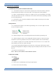
AutoBlock Plus Operation Manual and Instructions 1.4 Installing the Software 1.4.1 To install the software, insert the jump drive provided into the USB port of your computer. 1.4.2 Connect the AutoBlock to the computer using the USB cable provided. 1.4.3 Turn on the AutoBlock using the rocker switch located on the left side of the instrument. 1.4.4 Double-click on the “AutoBlock Installer” program. 1.4.5 Follow the prompts and click “Next” to continue through the install process. 1.4.
Environmental Express, Inc. 1.4.10 Paste in the System folder from the C://AutoBlock Software directory and over-write all files. 1.4.11 Once the software installation is complete, an AutoBlock icon will appear on your desktop. If the icon does not appear you can find the program by clicking on the Start button and proceeding to “Programs” in the menu. 1.4.12 Double-click on the AutoBlock icon to open the software.
AutoBlock Plus Operation Manual and Instructions 2.0 HOOKING UP INERT GAS TO THE AUTOBLOCK 2.1 Inert gas must be hooked up to the AutoBlock to prevent corrosion to the components in the cabinet of the unit. The gas must be inert (i.e. Nitrogen or Air) and from a source different from the air in the laboratory. NOTE: This gas must be flowing through the cabinet of the AutoBlock at all times, even when the unit is not running.
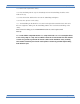
Environmental Express, Inc. 3.0 SERVICE SCREEN From the Main Screen, click on the Service Screen button for access to any service related items. 3.1 Reagents Tab 3.1.1 To assign a reagent to a specific port, click the drop-down arrow on the port number and select the appropriate reagent. The reagent is now assigned to that port. NOTE: Ports #1 and #6 will always be assigned to DI Water and cannot be changed. 3.1.2 To add a new reagent, click on the “ADD REAGENT” button. 3.1.2.
AutoBlock Plus Operation Manual and Instructions 3.2 Temperature Calibration Tab 3.2.1 The graphite block temperature should be calibrated on an annual basis and always performed when installing the AutoBlock for the first time. 3.2.2 In the Temp Cal screen, press the “ENABLE HEAT” button to heat the graphite block to 90°C. 3.2.3 Once the block has reached 90°C, allow it to stabilize for 15 minutes. 3.2.4 Read the temperature inside an empty well with an IR Thermometer traceable to NIST. 3.2.
Environmental Express, Inc. 3.3 Pump Calibration Tab 3.3.1 To calibrate the pump, inject 30mL of deionized water, using the manual screen (see Section 5.1), into a pre-weighed digestion vessel. Use Port 1 to calibrate Pump 1 and use Port 6 to calibrate Pump 2. 3.3.2 After injection, click the “Initialize” button to return the probe and racks to their home positions. 3.3.3 Weigh the vessel a second time and subtract the original weight to obtain the volume of deionized water injected. 3.3.
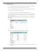
AutoBlock Plus Operation Manual and Instructions 3.4 Maintenance Tab 3.4.1 The Maintenance tab lists the items that require routine service. 3.4.2 Each service item lists the last date serviced, how often the service should take place, the number of days remaining until service is required, and an “Info” button describing what the service is. 3.4.3 When an item’s service is due the “Due?” column will change from a green “NO” to a red “YES”. 3.4.
Environmental Express, Inc. 3.5 Supplies Tab 3.5.1 The supplies tab lists part numbers and descriptions of items that may need to be replaced from time to time. If a part number you require is not listed on this tab contact Customer Service at 1-800-745-8218 to obtain a part number and price. All updated pricing can be found on the website at www.envexp.com. 3.5.2 Contact information for Environmental Express is also included on this tab. 3.6 Data Log Tab 3.6.
AutoBlock Plus Operation Manual and Instructions 4.0 CREATING A METHOD From the Main Screen, click on the Method Creation button. The AutoBlock will come with several pre-programmed EPA methods, however the software allows for users to create their own methods or modify existing ones. 1.5 Creating a Method 4.1.1 To create a method, press the “Delete All” button to clear the method template. 4.1.1.1 A prompt will appear asking the user if they want to delete all steps.
Environmental Express, Inc. 4.1.2.5 FILL: Final fill to volume. The user can choose what final volume the AutoBlock should fill all samples to, from 5 – 50mL. The reagent used for the fill step will always be deionized water from Port #1. In the event samples go to dryness during the digestion method one can choose whether or not the AutoBlock fills these cups to the desired final volume or not. 4.1.3 The user can move steps up or down in the method by clicking on the “Move Up” or “Move Down” buttons.
AutoBlock Plus Operation Manual and Instructions 4.2 Modifying an Existing Method 4.2.1 To modify an existing method, press the “LOAD” button and choose the appropriate method from the Methods folder to modify and click OK. 4.2.2 The method steps will appear on the screen. 4.2.3 Highlight any step and click “Edit Step” to make any necessary changes. Once the changes are complete click “OK”. 4.2.4 To delete a step highlight the step and click “Delete Step”. 4.2.
Environmental Express, Inc. 5.0 OPERATOR TEST From the Main Screen, click on the Operator Test button. 5.1 Select a method by clicking the “Select Method” button and choose the appropriate file from the Method folder. 5.1.1 The user can view this method by clicking the “View Method” button. No edits can be made to the method from this screen. 5.1.2 Ensure all method reagents match the reagents assigned to the ports of the AutoBlock. 5.
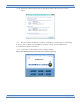
AutoBlock Plus Operation Manual and Instructions 5.4 Once ready, click “Start Method”. 5.5 A pre-test checklist will pop-up to prompt the user to check the reagent bottles and to ensure the door to the AutoBlock is closed. 5.6 The AutoBlock will track the total digestion time in the lower left corner of the screen. 5.7 If the AutoBlock detects any errors during operation, the unit will sound an audible alarm and immediately abort the method.
Environmental Express, Inc. 6.0 MANUAL OPERATION From the Main Screen, click on the Manual Screen button. The manual interface screen allows the user to manually perform all functions of the AutoBlock. It will be used for calibration steps and is also useful for troubleshooting. 6.1 Injecting a Reagent 6.1.1 To inject a reagent, choose the desired reagent from the reagent list by clicking on and highlighting it. 6.1.
AutoBlock Plus Operation Manual and Instructions 6.2 Heating the Graphite Block 6.2.1 To manually heat the graphite block, select the desired temperature in the “Temp Control” section of the screen. 6.2.2 Press “Enable Heat” and the block will heat to the desired temperature. 6.2.3 Press “Disable Heat” to turn the heat off. 6.3 Moving the Sample Probe 6.3.1 Designate the desired probe location by highlighting the cell on the cell position grid. 6.3.
Environmental Express, Inc. 7.4 Click on the desired file to open and click “OK”. 7.5 A .dat file is then displayed on the screen. One can print the data by pressing the “PRINT” button. 7.6 Users can also convert the .dat files to another format by right-clicking on the file name and saving as a different file type. www.envexp.
AutoBlock Plus Operation Manual and Instructions 8.0 TROUBLESHOOTING/MAINTENANCE 8.1 Cabinet Pressure – If air is not properly entering the cabinet of the AutoBlock the instrument will not allow the user to run a method. An error message will appear on the screen stating there is no airflow going into the cabinet and the method will be aborted. Go to the manual screen and observe the green and red indicator lights near the bottom of the screen. Look for “Cabinet Pressure”.
Environmental Express, Inc. 8.3 Changing the exhaust fan (only applicable to units with a fume hood) 8.3.1 Remove the front panel from the fume hood to access the hood chamber. 8.3.2 Remove the flexible exhaust tubing from the inlet side of the fan. 8.3.3 Disconnect the quick-disconnect wire from the fan to the AutoBlock. 8.3.4 Remove the two mounting screws holding the fan to the back of the fume hood. 8.3.5 Rotate the fan out of the exhaust port. It will slide out. 8.3.
AutoBlock Plus Operation Manual and Instructions 8.5 Changing the pump head 8.5.1 Remove the pump tubing (see section 8.4). 8.5.2 Remove the two mounting screws attaching the pump head to the AutoBlock. 8.5.3 Remove the pump head. 8.5.4 Insert a new pump head by lining up the mounting screws and lining up the drive screw. NOTE: It is important to line up the drive screw with the coupling of the pump motor. The left or right panels will need to be removed to do this properly.
Environmental Express, Inc. 10. WARNINGS AND NOTIFICATIONS 10.5 Electrical requirements 10.5.1 – Voltage: 120V, ~60Hz, 12A (Domestic) 10.5.2 – Voltage: 230V, ~50HZ, 6A (INTL) 10.5.3 - Power should not vary greater than 10%. Use the supplied power cord or equivalent to connect to the power supply. For safety reasons, a separate power receptacle should be provided for each SPE-Express. Do not use extension cords or outlet adaptors. Make certain that power outlets are earth-grounded at the grounding pin.
AutoBlock Plus Operation Manual and Instructions 10.12 The unit does not liberate any known poisonous substances. Caution is recommended as any exposed surface may have acid vapor residue due to usage. to maintain the maximum life of the electrical components, the inert gas line must remain connected and operational even when the unit is not in service. 10.12.1 – waste from the drain line should be neutralized and disposed of with a waste management service. 10.12.