
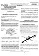
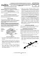
Instructions / Assembly


CEILING JOIST INSTALLATION
NOTE: This fixture can be installed into a ¾” thick furring strip, using
the pre-attached fast nails at the end of each hanger bar.
1. Choose the location for the fixture, taking into consideration the
required 7” clearance and the accessibility to the electrical
supply.
2. Raise the housing/hanger bar assembly to the desired location
between
the
two
ceiling
joists
Adjust
the
width
of
both
hanger
4. Place the housing and ceiling tile back into the drop ceiling.
Tightent the mounting flanges around each T-Bar to secure the
housing in place (FIG. 7).
5. Proceed to the “ELECTRICAL CONNECTIONS” section.
6. Proceed to the “TRIM INSTALLATION” section.
between
the
two
ceiling
joists
.
Adjust
the
width
of
both
hanger
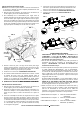
bars to the distance between the joists. Position the assembly so
that the mounting clips of the hanger bars cup underneath the
bottom edges of the joists. Hammer down the nails of the hanger
bars into the joists to secure the assembly into place.
(FIG. 3 & FIG. 4)
FIG. 5 FIG. 6
Hanger
FIG. 3
FIG. 7
Ba
r
Ceiling
Tile
Flange
Mounting
Flange
FIG. 4
Joist
Bottom edge
of joist
Nail
Mounting
Clip
T-bar
Mounting
Cli
p
Nail
Housing
Plaster
Frame
ELECTRICAL CONNECTIONS
WARNING: First disconnect electricity at the circuit breaker or
the fuse box. Disconnecting power by using the wall switch is
not sufficient to prevent electrical shock.
1. Using BX (armored) or NM (Romex) cable, run the supply wiring
from the power supply source to the fixture location.
WARNING - Use supply wires rated 90°C or higher.
3. Slide the plaster frame along the hanger bars to the desired
position. Using pliers squeeze the guides of the plaster frame
tightly around the hanger bars to lock the position of the plaster
f
Mounting
Clip
Joist
Hammer
Hanger bar
p
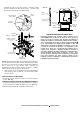
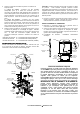
2. Open the hinged junction box’s door by lifting the metal latch.
A. FOR BX (ARMORED) CABLE - Break off one of the round
knockouts (FIG. 9) using a screwdriver. Secure an appropriately
sized BX cable connector to the knockout opening. Feed the BX
cable through the connector, providing 6” of slack inside the
junction box. Tighten the connector to secure the cable in place.
B. FOR NM (ROMEX) CABLE – Break off one of the rectangular
knockouts
located
on
the
top
of
the
junction
box
using
a
f
rame.
4. Proceed to the “ELECTRICAL CONNECTIONS” section.
5. Install the insulation around the housing, if desired. Install the
ceiling material, such as drywall, over the housing. A template is
provided to assist in making the holes in the ceiling material.
(NOTE: Blown-in Insulation may also be installed after the ceiling
material has been installed.)
6
Pd
t
th
“
TRIM
INSTALLATION
”
ti
knockouts
located
on
the
top
of
the
junction
box
using
a
screwdriver, creating a slot. (FIG. 8) Slide the NM cable into the
slot, as shown, making sure there is 6” of slack inside the
junction box. (FIG. 9)
3. Remove at least 3” of the cable’s outer sheath and remove the
plastic or paper over-wrap. Strip approximately 3/8” of insulation
from the ends of all supply wires. Using the provided “quick-
connect” wire connectors, make the following wire connections
within
the
junction
box
:
6
.
P
rocee
d
t
o
th
e
“
TRIM
INSTALLATION
”
sec
ti
on.
DROP CEILING INSTALLATION
1. Choose the location for the fixture, taking into consideration the
required 7” clearance and the accessibility to the electrical
supply.
2. Remove a ceiling tile from the T-bar grid at the installation
location. Using the provided template and a keyhole saw make
hl
t
th
did
lti
i
th
ili
til
within
the
junction
box
:
WHITE Fixture Wire to WHITE (NEUTRAL) Supply Wire
BLACK Fixture Wire to BLACK (HOT) Supply Wire
GREEN Fixture Wire to GREEN/BARE (GROUND) Supply Wire
ALL RIGHTS RESERVED. COPYRIGHT Envirolite 2020
a
h
o
l
ea
t
th
e
d
es
i
re
d
l
oca
ti
on
i
n
th
ece
ili
ng
til
e.
3. Place the housing/hanger bar assembly onto the ceiling tile into
the newly created hole. Adjust the width of both hanger bars to
the distance between the two T-bars, aligning each mounting clip
with the top of its corresponding T-bar. Bend the flanges on the
end of the T-Bar downwards. (FIG. 5 and FIG. 6) Bend the
mounting flanges at a 90 degree angle.