
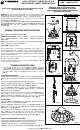
Installation Guide


________
DIMMING
Dimming performance may depend on the dimmer, the dimmer
range adjustment setting (for dimmers with brightness range
adjustments), the wiring method, and/or the number of LED
modules installed onto the dimmer circuit.
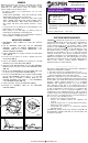
• For dimmer selection, it is recommended to use one of the
following dimmers:
Leviton Decora SureSlide® – 6631, 6674 (Universal); Leviton
IllumaTech® - IPI06-1L, IPL06-10 (Universal)
Lutron Ariandni®/Toggler® - TGCL-153P, AYCL-153P; Lutron
Diva® - DVWCL-153P, DVCL-153P; Lutron Luméa® - LGCL-
153P, Lutron Maestro® - MACL-153M; Lutron Skylark® - S-
600, S-603P, SCL-153P; Lutron Skylark Contour™ - CTCL-
153P.
• For best results, it is recommended to install a minimum of four
LED modules onto one dimmer.
• Before turning on the LED lights, set dimmer position at
maximum before adjusting to a lower light level.
• Please follow the dimming control manufacturer’s instructions
for the installation of all dimming controls.
_____________________
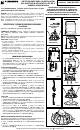
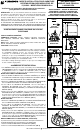
DRIVER REPLACEMENT
1. DISCONNECT MAIN POWER AT FUSE OR CIRCUIT
BREAKER.
2. Pull the RETROFIT TRIM down from the RECESSED
HOUSING. Unplug the FEMALE CONNECTOR of the
RETROFIT TRIM from the MALE CONNECTOR of the
SOCKET ADAPTER ASSEMBLY.
3. Pull the TRIM RING from magnets built into the CAST HEAT
SINK. (FIG. 6)
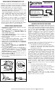
4. Press the four lens tabs in as shown to carefully remove the
plastic LENS. (FIG. 8)
5. Remove the DRIVER SCREWS and separate the old LED
DRIVER from the CAST HEAT SINK. (FIG. 8)
6. Detach the LED DRIVER WIRES from the LED TERMINAL
BLOCK by depressing down on the provided TERMINAL TABS.
(FIG. 10)
7. Mount the new LED DRIVER onto the CAST HEAT SINK using
the previously removed DRIVER SCREWS. (FIG. 8)
8. From the new LED DRIVER insert the RED (or BLACK) WIRE
into the HOT TERMINAL (marked with a “+” on the LED
BOARD) and the YELLOW (or WHITE) WIRE into the
NEUTRAL TERMINAL (marked with a “-” on the LED BOARD)
of the TERMINAL BLOCK. (FIG. 11)
9. Replace the LENS. Replace the TRIM RING. (FIG. 6)
10.Re-install the RETROFIT TRIM into the RECESSED
HOUSING. (FIG. 5)
_____________________________
FIVE-YEAR LIMITED WARRANTY
LiteChoice
warrants this product to be free from defects in
material and workmanship for five years from the original date of
purchase by the consumer. This warranty is limited to the
counter replacement at the time of purchase, with the original
purchase receipt. LiteChoice
will not be liable for the loss or
damage of any kind, incidental or consequential damages of any
kind, whether based on warranty contract or negligence, and
arising in connection with the sale, use or repair of the product
claimed to be defective. Some states do not allow the exclusion
or limitation of incidental or consequential damages so the above
limitation may not apply to you. This warranty gives you specific
legal rights and you may also have other rights, which vary from
state to state. Misuse, accident, improper installation or
maintenance will also void the warranty.
_____________________________
This device complies with part 15 of the FCC Rules. Operation is
subject to the following two conditions:
1. This device may not cause harmful interference, and
2. This device must accept any interference received, including
interference that may cause undesired operation.
NOTE: This equipment has been tested and found to comply
with the limits for a Class B digital device, pursuant to Part 15 of
the FCC Rules. These limits are designed to provide reasonable
protection against harmful interference in a residential
installation. This equipment generates, uses and can radiate
radio frequency energy and, if not installed and used in
accordance with the instructions, may cause harmful interference
to radio communications. However, there is no guarantee that
interference will not occur in a particular installation. If this
equipment does cause harmful interference to radio or television
reception, which can be determined by turning the equipment off
and on, the user is encouraged to try to correct the interference
by one or more of the following measures:
• Reorient or relocate the receiver antenna.
• Increase the separation between the equipment and
receiver.
• Install the product onto on a circuit different from that to
which the receiver is connected.
• Consult with the dealer or an experienced radio/TV
technician for help.
CAUTION: Any changes made to the electronics circuit will void
this equipment’s compliance with Part 15 of the FCC Rules and
should not be operated.
FIG. 10 FIG. 11
FIG. 9 FIG. 8
Class 2 Power Supply | Dry or Damp Location Only
CAUTION
DISCONNECT LINE VOLTAGE BEFORE INSTALLING OR
REPLACING
VEL12045120HDA-3
In: 15W, 0.15A
Out: 22-28V, 450mA
PF: >0.90
CONSTANT CURRENT
Dimmable LED Driver
120V 60Hz
RoHS
E339538
Santa Fe Springs, CA
www.espentech.com
V2 Toll Free 1-866-933-7736 Made in China
W Red
B Yel
N +
L -
ALL RIGHTS RESERVED LITECHOICE 2014