
Installation Guide


WARNING - RISK OF ELECTRIC SHOCK.
DISCONNECT MAIN POWER AT FUSE OR
CIRCUIT BREAKER BEFORE INSTALLING OR
SERVICING THE FIXTURE.
LED 6” RETROFIT TRIM INSTALLATION
INSTRUCTIONS - MODEL 9Y6WHWH-2Cxx
QUESTIONS? CALL TOLL
FREE 1-866-992-2278
ALL RIGHTS RESERVED LITECHOICE 2014
Please read carefully and save these instructions, as you
may need them at a later date.
GENERAL: All electrical connections must be in accordance with local and
National Electrical Code (N.E.C.) standards. If you are unfamiliar with proper
electrical wiring connections obtain the services of a qualified electrician.
Remove the trim from the box and make sure that no parts are missing by
referencing the PARTS illustrations.
THIS RETROFIT ASSEMBLY IS ACCEPTED AS A COMPONENT OF A LED
LUMINAIRE WHERE THE SUITABILITY OF THE COMBINATION SHALL BE
DETERMINED BY CSA OR CANADIAN AUTHORITIES HAVING
JURISDICTION.
__________________________________________
WARNING- RISK OF FIRE OR ELECTRIC SHOCK
For use with the following housing models:
COMMERCIAL ELECTRIC: CAT7IC, CAT7ICR, CAT7ICAT, CAT7ICRAT,
CAT7, HB5000S, HB5000SR, HBR5, HBR5R, HBR5ICAT, HBR5ICRA,
HBR5000SIC.
HALO: H7ICT, H7RICT, H7ICAT, H7RICAT,H7T, H7RT, H27RT, H5T, H5RT,
H5ICAT, H750ICAT, H750RICAT, H5RICAT.
LITECHOICE: HL6N8, HL6R8.
•Do not alter, relocate, or remove wiring, lampholders, power supply, or any
other electrical component. Installation of the retrofit assembly requires a
person familiar with the construction and operation of the luminaire’s electrical
system and the hazard involved. If not qualified, do not attempt installation.
Contact a qualified electrician.
•Do not make or alter any open holes in an enclosure of wiring or electrical
components during kit installation.
•To prevent wiring damage or abrasion, do not expose wiring to edges of
sheet metal or other sharp objects.
_____________________________
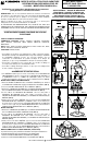
ASSEMBLY AND INSTALLATION
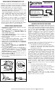
1. If the installed housing does not have TORSION SPRING SLOTS or
C-CLIPS (FIG. 5), then remove the SCREWS securing the TORSION
SPRINGS to the HEATSINK. Attach the FRICTION BLADES (included) to
the same location using the SCREWS that were previously removed.
(FIG. 7)
INCANDESCENT HOUSINGS
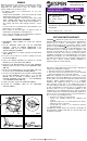
1.Unscrew the WING NUT inside the CAN to detach the SOCKET BRACKET
from the CAN. Disengage the SOCKET from the SOCKET BRACKET. (FIG.
2)
2.Thread the SOCKET ADAPTER into the SOCKET. (FIG. 3)
3.Plug the FEMALE CONNECTOR of the RETROFIT TRIM onto the MALE
CONNECTOR of the SOCKET ADAPTER ASSEMBLY. (FIG. 4)
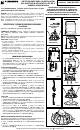
4.If using TORSION SPRINGS, squeeze both TORSION SPRING arms
together and insert into the TORSION SPRING SLOTS (or RECEIVER
BRACKETS) of the CAN. (FIG. 5)
5.Tuck all wires into the CAN and carefully push the RETROFIT TRIM into
CAN. (NOTE: To provide enough room in shallow cans, carefully position
SOCKET ADAPTER and SOCKET adjacent to the long side of the LED
DRIVER prior to inserting the RETROFIT TRIM into the CAN.) (FIG. 5)
LED HOUSINGS
1.Plug the FEMALE CONNECTOR of the RETROFIT TRIM onto the MALE
CONNECTOR of the HALO HOUSING. (FIG. 4)
2.If using TORSION SPRINGS, squeeze both TORSION SPRING arms
together and insert into the TORSION SPRING SLOTS (or RECEIVER
BRACKETS) of the CAN. (FIG. 5)
3.Tuck all wires into the CAN and carefully push the RETROFIT TRIM into
CAN. (NOTE: To provide enough room in shallow cans, carefully position
SOCKET ADAPTER and SOCKET adjacent to the long side of the LED
DRIVER prior to inserting the RETROFIT TRIM into the CAN.) (FIG. 5)
FACEPLATE REPLACEMENT (OPTIONAL)
This product is designed to allow the user to easily replace the magnetically
attached DECORATIVE FACEPLATE of the RETROFIT TRIM.
1.Pull off the FACEPLATE from the RETROFIT TRIM. (FIG. 6)
2.Attach the replacement FACEPLATE onto the RETROFIT TRIM. (FIG. 6)
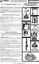
5 in. – 7 in.
6 in.
PARTS
SOCKET ADAPTER
ASSEMBLY
RETROFIT TRIM
COMPATIBLE HOUSING
DIMENSIONS
FIG. 6
FIG. 2
FIG. 4
FIG. 3
FIG. 5
OR
FIG. 7