
Installation Guide

WARNING - RISK OF ELECTRIC SHOCK.
DISCONNECT MAIN POWER AT FUSE OR CIRCUIT
BREAKER BEFORE INSTALLING OR SERVICING
THE FIXTURE.
LED 4” RETROFIT TRIM INSTALLATION
INSTRUCTIONS - MODEL 9Y4WHWH-2Cxx
QUESTIONS? CALL TOLL
FREE 1-866-992-2278
Please read carefully and save these instruc-
tions, as you may need them at a later date.
GENERAL: All electrical connections must be in accordance
with local and National Electrical Code (N.E.C.) standards. If
you are unfamiliar with proper electrical wiring connections
obtain the services of a qualified electrician.
Remove the trim from the box and make sure that no parts
are missing by referencing the PARTS illustrations.
THIS RETROFIT ASSEMBLY IS ACCEPTED AS A
COMPONENT OF A LED LUMINAIRE WHERE THE
SUITABILITY OF THE COMBINATION SHALL BE
DETERMINED BY CSA OR CANADIAN AUTHORITIES
HAVING JURISDICTION.
____________________________________
WARNING- RISK OF FIRE OR ELECTRIC
SHOCK
For use with the following housing models:
COMMERCIAL ELECTRIC: HBR2000B, HBR2000R,
HBR2000BICAT
HALO: H99T, H99RT, H99ICT, H99TAT, H99RTAT,
H99ICAT
LITECHOICE: HL4N8, HL4R8
• Do not alter, relocate, or remove wiring, lampholders,
power supply, or any other electrical component.
Installation of the retrofit assembly requires a person
familiar with the construction and operation of the
luminaire’s electrical system and the hazard involved. IF
NOT QUALIFIED, DO NOT ATTEMPT INSTALLATION.
CONTACT A QUALIFIED ELECTRICIAN.
• Do not make or alter any open holes in an enclosure of
wiring or electrical components during kit installation.
• To prevent wiring damage or abrasion, do not expose
wiring to edges of sheet metal or other sharp objects.
____________________________
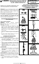
ASSEMBLY AND INSTALLATION
INCANDESCENT HOUSINGS
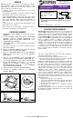
1. Unscrew the WING NUT inside the CAN to detach the
SOCKET BRACKET from the CAN. Disengage the
SOCKET from the SOCKET BRACKET. (FIG. 2)
2. Thread the SOCKET ADAPTER into the SOCKET. (FIG.
3)
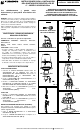
3. Plug the FEMALE CONNECTOR of the RETROFIT TRIM
onto the MALE CONNECTOR of the SOCKET ADAPTER
ASSEMBLY. (FIG. 4)
4. Tuck all wires into the CAN and carefully push the
RETROFIT TRIM into CAN. (FIG. 5)
LED HOUSINGS
1. Plug the FEMALE CONNECTOR of the RETROFIT TRIM
onto the MALE CONNECTOR of the HALO HOUSING.
(FIG. 4)
2. Tuck all wires into the CAN and carefully push the
RETROFIT TRIM into CAN. (FIG. 5)
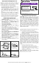
FACEPLATE REPLACEMENT (OPTIONAL)
This product is designed to allow the user to easily replace
the magnetically attached DECORATIVE FACEPLATE of the
RETROFIT TRIM.
1. Pull off the FACEPLATE from the RETROFIT TRIM. (FIG.
6)
2. Attach the replacement FACEPLATE onto the RETROFIT
TRIM. (FIG. 6)
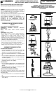
5 ½ in.
4 in.
FIG. 2
FIG. 3
PARTS
SOCKET ADAPTER
ASSEMBLY
COMPATIBLE HOUSING
DIMENSIONS
FIG. 5
RETROFIT TRIM
FIG. 4
FIG. 6
ALL RIGHTS RESERVED LITECHOICE 2014