
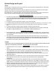
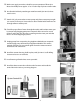
Installation manual


2 wire with ground
Romex cable
3 wire with ground
Romex cable
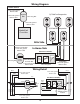
Power Source
Cooler
Control
Timer
2 Switch
3 Switch
Fan Timer & Switches
In from Junction Box
3 wire with ground
Romex cable
From Thermostat
to Switch Box
3 wire with ground
Romex cable
To Each Fan
2 wire with ground
Romex cable
In Home Side
Attic Side
QC1500 Fan Receptacles
3 wire with ground
Romex cable
Junction
Box
QuietCool
Control Box
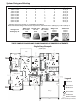
72
Black
Black
White
Green
Red
Yellow
Orange
Cooler
Control
Timer
2 Switch
3 Switch
(Line)
(Load)
Red
Black
Black
3 wire with ground
Romex cable
Red
Black
White
Green
Red
Red
Black
White
Green
Green
White
Green
Black
QC4500 Fan Receptacles
One Gang Box
3 wire with ground
Romex cable
2 wire with ground
Romex cable
Cap o
One Gang Box
Three Gang Box
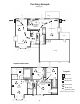
Typical wiring for
each fan receptical
installed
72
Wiring Detail
White
Wiring Diagram
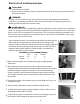
10
Fan Timer & Switches