
Specifications
LIST OF FIGURES
LIST OF TABLES
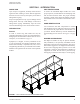
FIGURE 1 - Lifting Unit With Base Rails ...................................................................................................................9
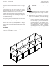
FIGURE 2 - Lifting Units Without Base Rails...........................................................................................................10
FIGURE 3 - Assembly, Units Without Base Rails .................................................................................................... 11
FIGURE 4 - Assembly, Units With Base Rails ......................................................................................................... 11
FIGURE 5 - Gasket Application ............................................................................................................................... 11
FIGURE 6 - Suspended Units .................................................................................................................................12
FIGURE 7 - Hand Identication ............................................................................................................................... 13
FIGURE 8 - Remove Hold Downs ........................................................................................................................... 14
FIGURE 9 - Isolator Installation ...............................................................................................................................14
FIGURE 10 - Drain Trap ..........................................................................................................................................15
FIGURE 11 - Mounting Sheaves .............................................................................................................................21
FIGURE 12 - Sheave Alignment ..............................................................................................................................22
FIGURE 13 - Split Tapper Sheave Mounting ...........................................................................................................22
FIGURE 14 - Belt Tension .......................................................................................................................................23
TABLE 1 - Minimum Hex Head Bolt Torque In Lb-Ft - Grade 5 Bolt .......................................................................18
TABLE 2 - Recommended Greasing Intervals Of Fan Bearings .............................................................................19
TABLE 3 - Recommended Greases For Various Operating Ranges ......................................................................20
TABLE 4 - Fan Bearing Maximum Grease Capacity ...............................................................................................20
TABLE 5 - Recommended Motor Greasing Schedule ............................................................................................21
TABLE 6 - Determining Deflection Force ................................................................................................................25
TABLE 7 - Forward Curve Fan Data .......................................................................................................................26
TABLE 8 - Vibration Levels .....................................................................................................................................26
TABLE 9 - MQL Troubleshooting Analysis ..............................................................................................................29
General ..................................................................................................................................................30
Water Cooling Coils ...............................................................................................................................30
Direct Expansion Coils ..........................................................................................................................30
Steam Coils ...........................................................................................................................................31
Water Heating Coils...............................................................................................................................32
SECTION 5 - TROUBLESHOOTING ......................................................................................................................33
TABLE OF CONTENTS (CONT’D)
JOHNSON CONTROLS
7
LIST OF FIGURES
FORM ET102.19-NOM1
ISSUE DATE:07/26/2013