
Specifications

JOHNSON CONTROLS
9
FORM ET102.19-NOM1 (809)
c. Cover entire equipment with protective tarp
or moisture proof cover. Extend cover under
equipment if stored on ground. Secure cover
with adequate tie downs or store indoors. Be
sure that all piping connections have protec-
tive shipping caps installed.
d. Monthly - remove cover from unit, open fan
access panel, remove belt ties and rotate fan
and motor slowly by hand to redistribute the
bearing grease and prevent bearing corro-
sion.
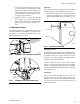
ASSEMBLING EQUIPMENT
All modules ship with the required bolts, nuts, screws
and gasket material to assemble the equipment. Bolt/
screw holes are accessible through the inside of the
upstream module (Fig’s 3 and 4).
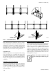
Gasketing
The gasketing material is supplied with each module for
sections that need to be assembled on the job site.
1. Gasket the perimeter of each module. Overlap the
gasketing approximately 1/8” when splicing. This
will prevent air leakage between modules (see Fig.
5).
Mounting Actuator
The Installing contractor takes all responsibility for the
mounting of all eld installed actuators. No requirements
are made for the position of these actuators due to the
number of options and arrangements available and the
assortment of specic applications.
Attention should be taken to insure proper actuator
support to prevent unnecessary stress in the linkage,
cabinet, or damper shaft. Multiple damper assemblies
must not be actuated from the shaft extension opposite
the connection link.
Mixing Box
Fresh air and return air dampers can be connected
together and driven from the same actuator if the
dampers are the same size. If the dampers are different
sizes they must be driven by individual actuators and
controlled separately.
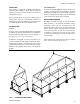
FIG. 3 - ASSEMBLY, UNITS WITHOUT BASE RAILS
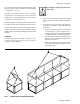
FIG. 4 - ASSEMBLY, UNITS WITH BASE RAILS
ATTACH CORNER
BRACKETS ON BOTH
MODULES WHEN
POSSIBLE
LD14004
LD14005
FIG. 5 - GASKET APPLICATION
1/8 MIN.
GASKET