
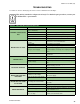
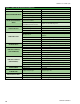
Specifications


JOHNSON CONTROLS
23
FORM ET102.19-NOM1 (809)
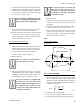
Direct Expansion Coils
1. The coil suction connection extended through the
end panel of the coil section. The coil distributor
is located inside the cabinet on the same side as
the suction connection.
2. DX coils are shipped capped and sealed with a
20 PSIG holding charge of dry nitrogen. Remove
nitrogen charge from coil by depressing Schraeder
stem, prior to cap removal.
3. Check nozzle in distributor for proper tonnage.
4. When a thermostatic expansion valve is supplied
with the unit, it will be shipped loose with the unit
and eld installation directly to the distributor will
be required.
5. Do not apply heat to the body or thermal element
of the expansion value. Wrap in wet rag while
brazing.
6. The thermostatic expansion valve must be of the
external equalizer tube type. Connect the ¼-inch
diameter external equalizer tube provided on the
coil to connection on expansion valve.
7. Care should be exercised when piping up the sys-
tem to be sure all joints are tight and all lines are
dry and free of foreign material.
Steam Coils
(maximum steam pressure is 15 PSIG)
1. Steam supply and steam return connections are
male N.P.T. copper pipe and are labeled on the end
panel of coil section. Connections extend through
coil section end panel.
2. When installing couplings, do not apply undue
stress to the connection extending through unit
panel. Use backup pipe wrench to avoid breaking
the weld between coil connection and header.
3. Support piping independently of coils and provide
adequate piping exibility. Stresses resulting from
expansion of closely coupled piping can cause
serious damage.
4. Do not reduce pipe size at the coil return connec-
tion. Carry return connection size through the dirt
pocket, making the reduction at the branch leading
to trap.
5. It is recommended that vacuum breakers be in-
stalled on all applications to prevent retaining
condensate in the coil. Generally, the vacuum
breaker is to be connected between the coil inlet
and the return main, the vacuum breaker should be
open to the atmosphere and the trap design should
allow venting of large quantities of air.
6. Do not drip supply mains through the coil.
7. Do not attempt to lift condensate when using
modulating or on/off control.
8. Size traps in accordance with manufacturers’
recommendations. Be certain that the required
pressure differential will always be available.
Do not undersize.
9. Float and thermostatic or bucket traps are recom-
mended for low-pressure steam. Thermostatic traps
should be used only for air venting.
10. Locate traps at least 12 inches below the coil return
connection.
11. Multiple coil installation.
a. Each coil or group of coils that is individually
controlled must be individually trapped.
b. Coils in series: Separate traps are required for
each coil, or bank of coils, in series.
c. Coils in parallel: A single trap may generally
be used but an individual trap for each coil is
preferred.
d. Do not attempt to lift condensate when using
modulating or on/off control.
12. With coils arranged for series airow, a separate
control is required on each back or coil in the direc-
tion of airow.
13. Modulating valves must be sized properly.
Do not undersize.