
Specifications


JOHNSON CONTROLS
22
FORM ET102.19-NOM1 (809)
Carefully read instructions for mixing
anti-freeze solution used. Some prod-
ucts will have a higher freezing point
in its natural state than when mixed
with water. The freezing of coils is not
the responsibility of ENVIRO-TEC
®
.
OPERATING GUIDELINES
Operating Limits
Do not exceed the operating limits in Table 7. A fan
wheel that is operated beyond the rpm and temperature
limits shown may suffer permanent distortion or
failure.
Vibration Levels
Each unit that is shipped has been trim-balanced to
function properly. Although the factory requirements
are much tighter, to assure satisfactory operation after
enduring the rigors of shipping and installation. The
following is accepted industry guidelines for eld-
balancing fans found in Table 8.
Vibration Causes
1. Wheel imbalance.
a. Dirt or debris on wheel blades.
b. Loose setscrews in wheel hub or bearing-to-
shaft.
c. Wheel distorted from over-speed.
d. Wheel balance weight missing.
2. Bent blower shaft.
3. Drive faulty.
a. Variable pitch sheaves - Axial and radial runout of
anges; uneven groove spacing; out of balance.
Also similar fault in driven sheave.
b. Bad V-belts; lumpy, or mismatched belts.
c. Belt tension too tight or loose.
4. Bad bearings, loose bearing hold-down bolts.
5. Motor imbalance.
6. Fan section not supported evenly on foundation.
7. Fan shaft not parallel with motor shaft.
Periodic Service and Maintenance
1. Check all moving parts for wear every six
months.
2. Check bearing collar, sheave, and wheel hub set-
screws, sheave capscrews, and bearing hold-down
bolts for tightness every six months.
APPLICATION RECOMMENDATION FOR COILS
Observe all local codes and industry
standards
General
Piping design, sizing, and installation information
presented in the ASHRAE Handbooks should, be
followed in the design and installation of piping.
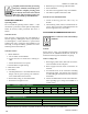
Water Cooling Coils
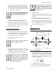
1. Water supply, water return, drain and vent connec-
tions are labeled on the end panel.
2. Water supply and water return connections are
checked.
3. Avoid undue stress to the connection extending
through unit panel. Use backup pipe wrench to
avoid breaking the weld between coils connection
and header.
4. Follow recommendations of the control manufac-
turer regarding types, sizing and installation of
control valves.
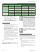
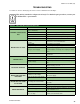
TABLE 7 - FORWARD CURVE FAN DATA
Diameter 9 x 4 9 x 6 10 x 7 12 x 9 12 x 12 15 x 11 18 x 13 18 x 18
Maximum RPM Class I 4800 3600 2800 2300 2000 1600 1200 1200
Maximum RPM Class II N/A N/A N/A N/A N/A 1700 1475 450
Note: Maximum air temperature through fan section is 225°F (107°C)
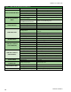
TABLE 8 - VIBRATION LEVELS
Fan Speed (RPM) Vibration
800 or less 5 mils maximum displacement
801 or greater .20 in/sec. Maximum velocity
Note: Excessive vibration from any cause contributes to premature fan and motor bearing failure. Overall, vibration levels
should be monitored every six months of operation. An increase in levels is an indication of potential trouble.