
Specifications

JOHNSON CONTROLS
19
FORM ET102.19-NOM1 (809)
7. Insert key (D) between the sheave and the shaft.
8. Tighten capscrews progressively with wrench. Do
this following a star pattern, taking a partial turn
on each capscrew successively until all are tight
(see Table 1 for proper torque).
Do not attempt to pull ange ush with
hub - some gap should remain between
ange and hub after tightening.
9. Put on belt and adjust belt tension properly. Refer
to Belt Section for tensioning instructions.
10. Be sure that all keys are in place. Be sure that all
setscrews and capscrews are torqued properly
before starting drive. Check setscrews and belt
tension after 24 hours of service.
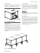
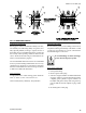
Adjust Variable Pitched Sheaves
(provided on motor only). See Fig. 10.
1. Slack off all belt tension by moving motor towards
blower shaft until belts are free of groove(s). For
easiest adjustment, remove belts from groove(s).
2. Loosen setscrew (B) in outer locking ring.
3. Loosen but do not remove capscrew.
4. Remove key (D).
This key projects a small amount to
provide a grip for removal.
5. Adjust pitch diameter by opening or closing the
movable ange(s) by a half or full turn. Opening
the ange(s) will decrease the blower speed, clos-
ing the ange(s) will increase blower speed.
Two groove sheaves are supplied with
both grooves set at the same pitch
diameter. Both movable anges must
be rotated the same number or turns
to ensure the same pitch diameter for
satisfactory operation.
Do not open sheaves more than ve
turns for “a” belt or 6 turns for “b”
belt. Doing so may cause the belts to
sit improperly, and cause the anges
to detach in service.
6. Replace key (D).
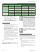
7. Tighten setscrew (B) in outer locking ring and
capscrew (C) with torque wrench to the values in
the Table 1.
8. Put on belts and adjust belt tension properly. Refer
to Belt Section for tensioning instructions.
9. Be sure that all keys are in place. Be sure that all
setscrews and capscrews are torqued properly
before starting drive. Check setscrews and belt
tension after 24 hours of service.
Belts
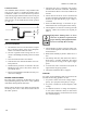
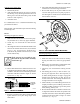
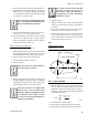
Adjusting Belt Tension.
See Fig. 13
FIG. 13 - BELT TENSION
1. Measuring belt span. Lay a tape measure along
the top of the belt, measure between the points at
which the outside of the belt meets the outside of
the sheaves. The following formula can be used to
calculate the belt span.
DEFLECTION FORCE
D
C
d
S
P
AN
LE
N
G
T
H
2
2
2
dD
CSpan
C = Center distance shaft to shaft
D = Driver sheave (large sheave) pitch diameter
d = Driver sheave (small sheave) pitch diameter
LD14011
LD14003