
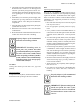
Specifications

JOHNSON CONTROLS
18
FORM ET102.19-NOM1 (809)
Without Grease Outlet Plug
1. Disassembly motor.
2. Add recommended amount of grease to bearing
and bearing cavity. (Bearing should be about 1/3
full of grease and outboard bearing cavity should
be about ½ full of grease.)
3. Assemble motor.
To re-lubricate the motor, consult the maintenance tag
provided on the motor.
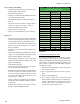
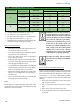
Refer to Table 1 for minimum torque of motor mounting
and bearing bolts.
Drives
Mounting Straight Bore Sheaves
1. Make sure there are no nicks or burrs on key, key-
way and shaft. If so, remove by proper methods.
2. Check key size with both the shaft and the
sheave.
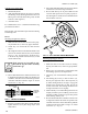
3. All straight bore sheaves should be mounted on the
motor or driver shaft with setscrew (A) toward the
motor (see Fig. 10). The sheave should be close
to the motor as possible with setscrew (A) in full
contact with the key.
If the setscrew (a) is not fully in con-
tact with the key, the sheave assembly
could come off.
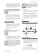
4. Be sure that both the driver and driven sheaves are
in alignment and that the shafts are parallel. The
centerline of the driver sheave must line up with the
centerline of the driven sheave. Angle “A” cannot
exceed 1/2º (see Fig. 11).
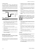
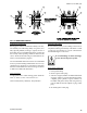
FIG. 11 - SHEAVE ALIGNMENT
5. Insert key (D) between the sheave and the shaft and
tighten setscrew (A) in place using torque value
from Table 1.
SHEAVE
CENTER
LINES
BELT CENTER
LINES
A
A
6. Put on belts and adjust belt tension properly. Refer
to Belt Section for tensioning instructions.
7. Be sure that all keys are in place. Make sure all
setscrews and capscrews are torqued properly be-
fore starting drive. Check setscrew and belt tension
after 24 hours of service.
FIG. 12 - SPLIT TAPPER SHEAVE MOUNTING
Mounting Split Tapper Sheaves
(See Fig. 12)
1. Make sure there are no nicks or burrs on the key,
keyway, and shaft. If so, remove by proper meth-
ods.
2. Remove any oils, lubricants or contaminants from
the bushing, capscrew, and tapered bore.
3. Check key size with both the bushing and the
shaft.
4. Put bushing (B) loosely in hub of sheave (A).
Do not press tight onto drive. Start capscrew (C)
by hand, turning them just enough to engage the
threads in the tapered holes on hub. Do not use
wrench at this time. The bushing should be loose
enough in the hub to move slightly.
5. Slide assembly on to shaft making allowance for
endplay of shaft to prevent rubbing. Do not force
assembly on shaft. If it does not go on easily, check
shaft, bushing, and key size.
6. Be sure that both the driver and driven sheaves are
in alignment and that the shafts are parallel. The
centerline of the driver sheave must line up with the
centerline of the driven sheave. Angle “A” cannot
exceed 1/2º (see Fig. 11).
LD14010