
Specifications

JOHNSON CONTROLS
12
FORM ET102.19-NOM1 (809)
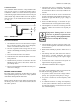
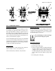
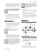
Condensate Drain
All condensate drains must have a trap installed. This
will prevent excessive condensate buildup and/or
condensate overow. To ensure that the trap remains
sealed the trap depth and the distance between the pan
outlet and the trap outlet should be twice the negative
static pressure of coil module under normal operation
(see Fig. 9).
FIG. 9 - DRAIN TRAP
Electrical Installation
1. The Electrical service to the fan must be compat-
ible to the rated voltage on the motor nameplate,
and be in accordance with local codes.
2. The Fan segments metal casing must be con-
nected to the buildings electrical ground on isolated
units.
3. Door electrical interlock is not offered.
4. Some motors have internal automatic reset over-
load protection.
5. Thermal motor protection is external to the unit.
Thermal protection and a disconnect switch are
provided by others.
6. Review wiring diagram and make necessary con-
nections accordingly.
BEFORE START-UP CHECK
Thorough safety precautions should always be taken
when performing startup and service. Only qualied
individuals should perform these tasks.
Before entering the fan section, make sure that the fan
electrical power source is disconnected and locked in
the “OFF” position.
1. Check that the unit is completely and properly
installed with ductwork connected. Check that
all construction debris is removed, and lters are
cleaned.
2. Check that all electrical work is finished and
properly terminated. Check that all electrical con-
nections are tight and that the proper voltage is
connected.
3. Motor and Ball bearings on fan shaft are pre-
lubricated and do not need grease before startup.
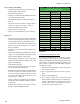
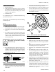
4. Check tightness of setscrews in bearings and fan
wheel(s). Make sure setscrews are torqued per
Table 1.
Equipment damage due to loose
setscrews or fasteners represents im-
proper start-up and equipment abuse.
It is not covered by the warranty.
5. Check tightness of sheave setscrews and/or cap-
screws. Check alignment of fan and motor sheaves
and belt tension.
6. Rotate shaft manually by hand to make sure it is
free.
7. Fan Startup: Start Fan, and observe the rotation.
If the fan is operating backward, disconnect
power and reverse two legs of the 3-phase supply
power.
8. To ensure that water connections and joints are
tight, leak test the piping systems.
9. Check that condensate drain is trapped.
START-UP
AC power current imbalance must not exceed 2%. Be
sure that the following guidelines are met:
1. AC power is within 10% of rate voltage with fre-
quency. (See equipment nameplate for ratings).
2. AC power is within 5% of rated frequency with
voltage.
3. A combined variation in voltage and frequency
of 10% (sum of absolute values) of rated values
provided the frequency variation does not exceed
5% of rated frequency.