
Specifications

JOHNSON CONTROLS
11
FORM ET102.19-NOM1 (809)
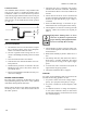
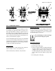
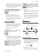
Internal Isolation
Equipment may be supplied with internal spring
isolation. If so, removal of shipping hold-downs is
required before equipment start-up (see Fig. 7).
FIG. 7 - REMOVE HOLD DOWNS
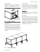
External Isolation
Install vibration isolators (see Fig. 8) in accordance with
the job specications and the instructions of the isolator
manufacturer base. Base rails are required for external
isolation. If the coil module is also isolated, the piping
must be isolated or have a exible connection to prevent
coil header damage due to equipment movement. All
piping, wiring, ductwork and external connections must
be isolated.
Service Clearance
Access to at least one side of the equipment is
required for routine service, maintenance and repair.
Consideration should be given to fan shaft, coil, lter
removal, motor, fan, bearings, and damper linkage
access. Clearance must meet or exceed applicable local
and national codes.
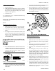
Panel Removal
To remove access panels, loosen the four retaining
screws and lift panel off. Alternately, lift off hinges with
quick turn fasteners.
General Piping
All pipe connections need to be supported independently
from the header. Failure to do so may cause cracking
at the headers. All piping shall be in accordance with
local codes and follow accepted industry standards. DX
coil distributor cap for test and nitrogen charge must be
removed before mounting TXV. All coil connections
are stubbed out of cabinet panel with the exception of
refrigerant (DX) coils. Field penetration of panels is
required for liquid line piping.
LD14007
FIG. 8 - ISOLATOR INSTALLATION
SHIPPING HOLD-DOWNS-
REMOVE BEFORE START-UP
EXTRA HOLD-DOWN
ON SIZES 10 & ABOVE