
Specifications

JOHNSON CONTROLS
10
FORM ET102.19-NOM1 (809)
INSTALLATION
This equipment must be installed in strict accordance
with any applicable local, state, and national codes
including but not limited to building, electrical, and
mechanical codes. On single wall equipment, lay
rigid temporary protection, such as plywood, inside of
equipment to protect insulation during installation.
Suspended Units
When the equipment is to be suspended from a ceiling,
a base rail, angle iron, or channel must support the
equipment. The MQL product line is not designed to
be suspended from the top of the equipment. Before
hanging the equipment, all eld assembly must be
completed.
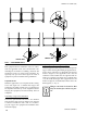
Suspending Using Factory Base Rail
The factory optional base rails have a 5/8” diameter
hole located in each corner for hanger rods. A hanger
rod must be installed in each corner of a module to
properly support the equipment and maintain unit’s
structural integrity.
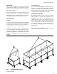
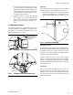
Suspending Using Field Supplied Supports
All eld supplied structural supports must be designed to
support entire unit weight including all appurtenances,
motor, drives, and all live or dead loads. All supports
must be designed to meet applicable local codes and
ordinances. Each module must be supported with an
angle iron or channel. The angle iron or channel must
cover the width and length of the equipment base and
must be designed to mechanically lock the unit to the
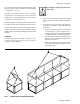
eld supports (see Fig. 6).
Hanger rods must be located so that
they do not interfere with access pan-
els.
FIG. 6 - SUSPENDED UNITS
SIDE OF UNIT
SIDE OF UNIT
LD14006