BY JOHNSON CONTROLS Installation, Operation & Maintenance INDOOR AIR HANDLING UNIT ET102.19-NOM1 (209) Model MQL SERIES B Form ET102.
FORM ET102.19-NOM1 (809) TABLE OF CONTENTS TABLE OF CONTENTS..................................................................................................................2 LIST OF FIGURES..........................................................................................................................4 LIST OF TABLES............................................................................................................................4 SAFETY SYMBOLS . .......................................
FORM ET102.19-NOM1 (809) TABLE OF CONTENTS (cont.) PERIODIC MAINTENANCE AND SERVICE................................................................................13 General..................................................................................................................................................13 After 48 Hours of Operation................................................................................................................13 Weekly.........................................
FORM ET102.19-NOM1 (809) LIST OF FIGURES FIG. 1 - LIFTING WITH BASE RAILS..........................................................................................7 FIG. 2 - lIFTING UNITS WITHOUT BASE RAILS.......................................................................8 FIG. 3 - ASSEMBLY, UNITS WITHOUT BASE RAILS.................................................................9 FIG. 4 - ASSEMBLY, UNITS WITH BASE RAILS........................................................................9 FIG.
FORM ET102.19-NOM1 (809) SAFETY SYMBOLS The following symbols are used in this document to alert the reader to areas of potential hazard: DANGER indicates an imminently hazardous situation which, if not avoided, will result in death or serious injury. CAUTION identifies a hazard which could lead to damage to the machine, damage to other equipment and/or environmental pollution. Usually an instruction will be given, together with a brief explanation.
FORM ET102.19-NOM1 (809) SAFETY CONSIDERATIONS The equipment covered by this manual is designed for safe and reliable operation when installed and operated within its design specification limits. To avoid personal injury or damage to equipment or property while installing or operating this equipment, it is essential that qualified, experienced personnel perform these functions using good judgment and safe practices. See the following cautionary statements. ELECTRICAL SHOCK HAZARDS.
FORM ET102.19-NOM1 (809) INSPECTION Unit Identification Upon receipt of equipment, carefully check all items against the bill of lading to ensure that all equipment has been received. Note any discrepancy on the bill of lading before signing. To ensure the assembled MQL modules are in the proper sequence, each module has an identifying code and an airflow direction label. The proper assembly sequence is listed on the supply fan nametag.
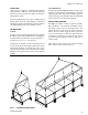
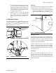
FORM ET102.19-NOM1 (809) Units without base rails must be lifted with slings. Place slings at ends and joints of modules to prevent damage to equipment (see Fig. 2). Spreader bars should be used to prevent damage to equipment. Avoid twisting or uneven lifting of equipment. Do not lift equipment by coil connection or headers. See submittal drawings. If transporting units with forklift, forks must extend the full width of unit to prevent damage to bottom of unit.
FORM ET102.19-NOM1 (809) c. Cover entire equipment with protective tarp or moisture proof cover. Extend cover under equipment if stored on ground. Secure cover with adequate tie downs or store indoors. Be sure that all piping connections have protective shipping caps installed. d. Monthly - remove cover from unit, open fan access panel, remove belt ties and rotate fan and motor slowly by hand to redistribute the bearing grease and prevent bearing corrosion.
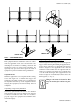
FORM ET102.19-NOM1 (809) SIDE OF UNIT SIDE OF UNIT LD14006 fig. 6 - suspended units INSTALLATION Suspending Using Field Supplied Supports This equipment must be installed in strict accordance with any applicable local, state, and national codes including but not limited to building, electrical, and mechanical codes. On single wall equipment, lay rigid temporary protection, such as plywood, inside of equipment to protect insulation during installation.
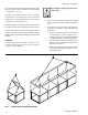
FORM ET102.19-NOM1 (809) Internal Isolation Service Clearance Equipment may be supplied with internal spring isolation. If so, removal of shipping hold-downs is required before equipment start-up (see Fig. 7). Access to at least one side of the equipment is required for routine service, maintenance and repair. Consideration should be given to fan shaft, coil, filter removal, motor, fan, bearings, and damper linkage access. Clearance must meet or exceed applicable local and national codes.
FORM ET102.19-NOM1 (809) Condensate Drain All condensate drains must have a trap installed. This will prevent excessive condensate buildup and/or condensate overflow. To ensure that the trap remains sealed the trap depth and the distance between the pan outlet and the trap outlet should be twice the negative static pressure of coil module under normal operation (see Fig. 9). 1. Check that the unit is completely and properly installed with ductwork connected.
FORM ET102.19-NOM1 (809) FIRST TIME MOTOR STARTUP Check to see that all power to the equipment is off. Be sure that the motor shaft is disconnected from the load, and will not cause fan rotation. 1. Make sure that the mechanical installation is secure. All bolts and nuts are tightened etc. 2. Ensure that all construction debris is removed from inside of equipment. 3. Check lubrication of fan, motor bearings and damper linkage a.
FORM ET102.19-NOM1 (809) Every Three to Six Months • Check fan bearing grease line connections. Lines should be tight to the bearings. • Re-lubricate fan bearings. • Check motor lubrication. Recommendations are provided on the motor label. • Check bearing and motor bracket bolt torque (see Table 1). • Align fan and motor sheaves. Tighten sheave setscrews to the proper torque (see Table 1). • Check and adjust fan belt tension.
FORM ET102.19-NOM1 (809) 5. Thoroughly clean the contaminated area with mild bleach and water solution or an EPA-approved sanitizer specifically designed for HVAC use. Carefully follow the sanitizer manufacturer instructions regarding the use and the disposal of their product. 6. Immediately rinse the drain pan thoroughly with fresh water to prevent potential corrosion from the cleaning solution of the drain pan and drain line components. 7.
FORM ET102.19-NOM1 (809) Fan Bearings Bearing Set Screw Alignment Align bearing setscrews. See Table 1 for bearing setscrew torque. Fan Bearings should be lubricated with a lithium base grease which conforms to NLGI Number 2 for consistency. See Tables 2, 3 and 4 for recommended greasing intervals, operating range, and bearing grease capacities.
FORM ET102.19-NOM1 (809) fig. 10 - mounting sheaves Lubrication and Bearings Lubrication Procedure Bearing grease will lose its lubrication ability over time, not suddenly. The lubricating ability of a grease (over time) depends primarily on the type of grease, the size of the bearing, the speed at which the bearing operates and the severity of the operating conditions. Good results can be obtained if the following recommendations are used in your maintenance program.
FORM ET102.19-NOM1 (809) Without Grease Outlet Plug 1. Disassembly motor. 2. Add recommended amount of grease to bearing and bearing cavity. (Bearing should be about 1/3 full of grease and outboard bearing cavity should be about ½ full of grease.) 3. Assemble motor. 6. Put on belts and adjust belt tension properly. Refer to Belt Section for tensioning instructions. 7. Be sure that all keys are in place. Make sure all setscrews and capscrews are torqued properly before starting drive.
FORM ET102.19-NOM1 (809) 7. Insert key (D) between the sheave and the shaft. 8. Tighten capscrews progressively with wrench. Do this following a star pattern, taking a partial turn on each capscrew successively until all are tight (see Table 1 for proper torque). Do not open sheaves more than five turns for “a” belt or 6 turns for “b” belt. Doing so may cause the belts to sit improperly, and cause the flanges to detach in service.
FORM ET102.19-NOM1 (809) Table 6 - DETERMINING DEFLECTION FORCE Belt Cross Section Smallest Sheave Diameter Range RPM Range 3.0 - 3.6 A New Belt 400 - 2500 2501 - 4000 3.7 2.8 5.5 4.2 3.8 - 4.8 400 - 2500 2501 - 4000 4.5 3.8 6.8 5.7 5.0 - 7.0 400 - 2500 2501 - 4000 5.4 4.7 8.0 7.0 4.4 - 5.6 860 - 2500 2501 - 4000 5.3 4.5 7.9 6.7 5.8 - 8.6 860 - 2500 2501 - 4000 6.3 6.0 9.4 8.9 B 2. Calculate deflection (Deflection = Span ÷ 64) 3. See Table 6 for correct deflection force. 4.
FORM ET102.19-NOM1 (809) 5. Use a steam-cleaning machine, starting from the top of the coil and working downward. Clean the leaving airside of the coil first, then the entering airside. Use a block-off to prevent steam from blowing through the coil and into dry sections of the unit. 6. Repeat step 5 as necessary. 7. Confirm that the drain line is open following the cleaning. 8. Allow the unit to dry thoroughly before putting the system back in service. 9.
FORM ET102.19-NOM1 (809) Carefully read instructions for mixing anti-freeze solution used. Some products will have a higher freezing point in its natural state than when mixed with water. The freezing of coils is not the responsibility of ENVIRO-TEC®. OPERATING GUIDELINES Operating Limits Do not exceed the operating limits in Table 7. A fan wheel that is operated beyond the rpm and temperature limits shown may suffer permanent distortion or failure. 4. 5. 6. 7.
FORM ET102.19-NOM1 (809) Direct Expansion Coils 1. The coil suction connection extended through the end panel of the coil section. The coil distributor is located inside the cabinet on the same side as the suction connection. 2. DX coils are shipped capped and sealed with a 20 PSIG holding charge of dry nitrogen. Remove nitrogen charge from coil by depressing Schraeder stem, prior to cap removal. 3. Check nozzle in distributor for proper tonnage. 4.
FORM ET102.19-NOM1 (809) 14. Freezing conditions (entering air temperature below 35ºF) a. 5-psi steam must be supplied to coils at all times. b. Modulating valves are not recommended. Control should be by means of face and bypass dampers. c. Consideration should be given to the use of two or three coils in series with two position steam control valves on that coil or coils which will be handling 35ºF, or colder, air.
FORM ET102.19-NOM1 (809) TROUBLESHOOTING Use Table 9 to assist in identifying the cause or cause of malfunction in the MQL. This table is intended as a diagnostic aid only. For detailed repair procedures, contact your ENVIRO-TEC ® representative. Table 9 - MQL Troubleshooting Analysis SYMPTOM Bearing is excessively hot PROBABLE CAUSE Allow machine to cool down and restart. Over-lubrication. Clean surfaces of grease and purge. Over tensioned belts. Adjust belt tension. No lubrication.
FORM ET102.19-NOM1 (809) Table 9 - MQL Troubleshooting Analysis SYMPTOM Excessive motor noise Rapid motor bearing wear Loose fan belt Short belt life Bearing noise Low coil capacity (Chilled water) Low coil capacity (Refrigerant) Drain pan is overflowing Standing water in drain pan Excess dirt in unit Mold inside air handler 26 PROBABLE CAUSE RECOMMENDED ACTION Motor mounting bolts loose. Tighten motor mounting bolts. Rigid coupling connections. Replace with flexible connections.
FORM ET102.
©2009 Johnson Controls, Inc. P.O. Box 423, Milwaukee, WI 53203 www.johnsoncontrols.com Printed in USA ET102.19-NOM1 (809) Supersedes ET102.