
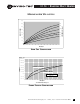
Troubleshooting guide

ELECTRIC DUCT HEATER • I.O.M.
8
Electric Duct Heater IOM • ©June, 2001 • Environmental Technologies, Inc.
MINIMUM WIRE GAUGE
(from Table 310-16 NEC 1996 wire rated 75°C)
AMPERES MINIMUM WIRE GAUGE AMPERES MINIMUM WIRE GAUGE
20 14 AWG 175 2/0 AWG
25 12 AWG 200 3/0 AWG
35 10 AWG 230 4/0 AWG
50 8 AWG 255 250 kcmil
65 6 AWG 285 300 kcmil
85 4 AWG 310 350 kcmil
100 3 AWG 335 400 kcmil
115 2 AWG 380 500 kcmil
130 1 AWG 420 600 kcmil
150 1/0 AWG
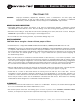
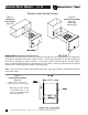
FIELD WIRING
NOTE: Prior to installing any wiring, check the unit name plate for main power voltage, control voltage and maximum
overcurrent protection. Operating a heater at other than the specified voltage and phase can result in fire or electrical hazard.
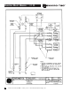
All field wiring must comply with NATIONAL ELECTRIC CODE and local code requirements. A point-to-point wiring diagram is
located on the inside of the control panel door, which details wiring and field wire gauge.
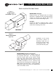
• Use copper conductors only with a minimum of 75°C insulation.
• Tighten all wiring lugs and terminals prior to connecting power to the unit, as they may loosen during transportation.
• Connect the power lines to the power distribution terminals inside the control enclosure and tighten to 35 inch-pounds
(.4kg meters). If a factory wired disconnect switch is installed, connect the power lines to the line side of the switch. The line
block or disconnect is rated at 125% of nominal heater amperes based on 75°C wire.
• Mount and wire any field installed items as indicated on the factory supplied wiring diagram. When mounting field installed
components, do not jumper out or rewire any factory wiring without written approval from Environmental Technologies, Inc.
only. Violation will void warranty and listing.
• Energize unit and check all controls for proper operation. Do not operate unit without proper airflow.
ELECTRIC HEATER PREVENTATIVE MAINTENANCE CHECKS & SERVICE SCHEDULE
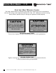
CAUTION!
DISCONNECT ALL POWER SOURCES BEFORE ATTEMPTING TO SERVICE OR CLEAN HEATER
Before, and at Midpoint of the Heating Season:
• Check all electrical connections for tightness and broken terminations.
• Check all wiring for deterioration or over heating.
• Check unit for dirt or dust, and wipe clean (except elements).
• Check the element section for obstructions and debris.
• Check all components for wear and physical damage.
• Check all safety devices for proper operation.
• Check temperature controls for proper operation.
CAUTION:
In the event of thermal protection failure, it is recommended that a qualified service person
investigate the cause of failure prior to returning the heater to normal service.
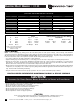
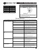
POWER WIRING CONTROL WIRING TRANSFORMER WIRING
Stages Primary Voltage (same as Power Wiring)
L1 Black Step 1 Red SECONDARY
L2 Red Step 2 Purple 24 Volt 277 & 120 Volt
L3 Blue Step 3 Orange Negative Yellow Negative Red
N White Step 4 Brown Positive Blue Positive Black
Ground Green Fan Output Black
NOTE: Units with wire gauges
8 and greater will be color
coded with tape.