ELECTRIC DUCT HEATERS INSTALLATION, OPERATION AND MAINTENANCE MANUAL Stock ID: IOM-EDH Reprinted June, 2001 ©2001 Environmental Technologies, Inc. Largo, FL • Part No.
ELECTRIC DUCT HEATER • I.O.M. TABLE OF CONTENTS DESCRIPTION PAGE Pre Start-Up ........................................................................................................................................3 Receiving and Inspection ....................................................................................................................3 Unit Placement ...................................................................................................................................
I.O.M. • ELECTRIC DUCT HEATER PRE START-UP WARNING: Improper installation, adjustments, alterations, service or maintenance can cause injury and property damage, as well as possible voiding of factory warranty. For assistance or additional information, consult a qualified contractor and your local ENVIRO-TEC® representative. RECEIVING AND INSPECTING • Thoroughly examine the exterior and interior of all units for transportation damage. If damage is found, immediately file a claim with the carrier.
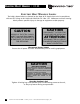
ELECTRIC DUCT HEATER • I.O.M. ELECTRIC HEAT WARNING LABELS The labels shown below are located on the door of all electric heat units in compliance with our ETL listings to UL 1996 and CAN/CSA C22.2 No. 155. Adherence to these warning labels prevents possible injury or damage to equipment and/or property. CAUTION CAUTION HAZARD OF ELECTRIC SHOCK. MORE THAN ONE DISCONNECT SWITCH MAY BE REQUIRED TO DE-ENERGIZE THE EQUIPMENT FOR SERVICING. DISCONNECT THE ELECTRIC POWER BEFORE SERVICING.
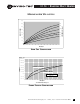
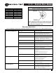
I.O.M. • ELECTRIC DUCT HEATER MINIMUM AIR VELOCITIES 1600 60 VELOCITY (FPM) 1200 1000 40 800 25 10 600 0 ENTERING AIR (Deg. F) 80 1400 400 200 0 0 2 4 6 8 10 12 14 16 18 20 22 24 KW/SQ FT. OPEN COIL CONSTRUCTION M/MIN. FPM 304.8 1000 274.2 900 243.6 800 VELOCITY 213.0 700 HORIZONTAL AIRFLOW 182.4 600 152.4 500 121.8 400 VERTICAL AIRFLOW 91.2 300 INLET AIR TEMPERATURE 77°F, 25°C 60.6 200 30.0 100 0 1 2 3 4 5 6 7 8 9 10 11 12 13 14 15 KW/SQ FT. 15.
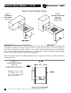
ELECTRIC DUCT HEATER • I.O.M. INSTALLATION INSTRUCTIONS Figure 1 Horizontal Duct Heater (Type SS) Figure 2 Vertical Duct Heater (Type VS) Vertical Up Airflow Only Model EDHSS (Side Slip-In, Vertical Slip-In) Installation of the slip-in heater consists of cutting an opening in the duct approximately 1/4" larger than the height and width of the heater element section. Insert heater and fasten to the duct using sheet metal screws through the control enclosure.
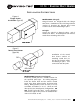
I.O.M. • ELECTRIC DUCT HEATER INSTALLATION INSTRUCTIONS Figure 4 Flange Heater Installation (Type SF) Model EDHSF (Flanged) Flanged heaters are designed with the flanges turned out. Installation of the side flanged heater consists of inserting the flanged duct heater section into the duct and bolting in place. Raintight Heaters are sealed in a flanged section. Unit is mounted as above. A weatherproof seal must be made when mounting these units.
ELECTRIC DUCT HEATER • I.O.M.
I.O.M. • ELECTRIC DUCT HEATER Figure 6 Airflow Switch Probe Reversal AMPERE READING PER KW VOLTAGE/PHASE AMPERES/KW 120 / 1 8.33 208 / 1 4.80 240 / 1 4.16 277 / 1 3.61 480 / 1 2.08 208 / 3 2.77 240 / 3 2.40 480 / 3 1.202 Airflow switch probe is installed in accordance with the specification. If application dictates opposite airflow, rotate the probe 180°. Directional arrow is stamped on airflow sensing probe. DOES NOT APPLY TO VERTICAL UNITS.
ELECTRIC DUCT HEATER • I.O.M. 10 Electric Duct Heater IOM • ©June, 2001 • Environmental Technologies, Inc.
I.O.M. • ELECTRIC DUCT HEATER Environmental Technologies, Inc.
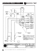
ELECTRIC DUCT HEATER • I.O.M. PROPORTIONAL HEAT CONTROL (SSR) TROUBLESHOOTING GUIDE CAUTION: Lethal voltages are present in the heater control enclosure. Use extreme caution when taking measurements in these units. Always disconnect power before removing or re-applying any connections. 1. Before applying power, verify wiring matches diagram in cover of heater control enclosure, and that correct line voltage has been wired to heater line block. 2.
I.O.M. • ELECTRIC DUCT HEATER 8. If the heater always remains energized when power is applied, remove the wire from P4 of the interface circuit board. If the heat remains on, there is a wiring error or the SSR is defective. CAUTION: Remove Power From the Unit Before Proceeding With the Next Step. 9. If the heater is always de-energized when power is applied, remove the line and load connections to the proportional heat control and temporarily tie them together.
ELECTRIC DUCT HEATER • I.O.M. VERNIER HEAT CONTROL TROUBLESHOOTING GUIDE CAUTION: Lethal voltages are present in the heater control enclosure. Use extreme caution when taking measurements in these units. Always remove power before removing or re-applying any connections. 1. Before applying power, verify wiring matches diagram in cover of heater control enclosure, and that correct line voltage has been wired to heater line block. NOTE: Polarity of the 24 VAC signal is important.
I.O.M. • ELECTRIC DUCT HEATER SAFETY CONSIDERATIONS The equipment covered by this manual is designed for safe and reliable operation when installed and operated within its design specification limits. To avoid personal injury or damage to equipment or property while installing or operating this equipment, it is essential that qualified, experienced personnel perform these functions using good judgement and safe practices. See the following cautionary statements. DANGER ELECTRICAL SHOCK HAZARDS.