
Operating instructions
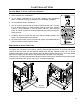
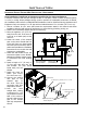

A Fresh-air intake is strongly recommended for all
installations. Failure to install intake air may result in
improper combustion as well as the unit smoking during
power failures.
The inlet to the intake must be below and a minimum of
12” (30cm) away from the unit exhaust outlet.
Outside fresh air is mandatory when installing this
unit in airtight homes and mobile homes.
When connecting to an outside fresh air source, do not use
plastic or combustible pipe. A 1⅝” minimum (42 mm) ID
(inside diameter) steel, aluminum or copper pipe should be
used. It is recommended, when you are installing a fresh
air system, to keep the number of bends in the pipe to a
minimum.
Installation
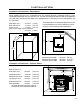
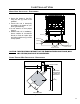
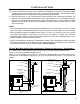
outSiDe fReSh-aiR connection:
1
5
/8" ID
(42 mm)
Optional
Elbow
Outside
Wall
Figure 17: Outside Air Connection.
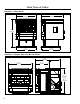
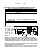
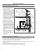
exhauSt anD fReSh aiR intake locationS:
EXHAUST Freestanding Fireplace Insert Built-In Heater
Base of unit to center of flue 16 ⅜” (41.5 cm) 9” (22.8 cm) 10 ¾” (27.3 cm)
Side of unit to center of flue 5
3
/16” (13.2 cm) 5
3
/16” (13.2 cm) 5
3
/16” (13.2 cm)
Center of unit to center of flue 5 ¾” (14.6 cm) 5 ¾” (14.6 cm) 5 ¾” (14.6 cm)
FRESH AIR INTAKE.
Base of unit to center of intake 10 ¾” (27.3 cm) 3 ⅜” (7.4 cm) 5 ⅛” (8.6 cm)
Side of unit to center of intake 12” (30.4 cm) 12” (30.4 cm) 12” (30.4 cm)
Center of unit to center of intake 1” (2.5 cm) 1” (2.5 cm) 1” (2.5 cm)
16
3
/8"
(415 mm)
10
3
/4"
(273 mm
)
5
3
/16"
(132 mm
)
12"
(304 mm)
5
3
/4"
(146 mm
)
1"
(25 mm)
Insert
9" (228 mm)
Heater
10
3
/4" (273 mm)
5
3
/16"
(132 mm)
12"
(304 mm)
Insert
3
3
/8" (86mm)
Heater
5
1
/8" (131 mm)
5
3
/4"
(146 mm)
1"
(25 mm)
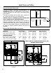
Figure 18: EF3 Freestanding Inlet and Outlet
Location.
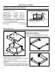
Figure 19: EF3 Fireplace Insert Inlet and Outlet Location.
INSTALL VENT AT CLEARANCES SPECIFIED BY THE
VENTING MANUFACTURER
16