
Operating instructions


Installation
Failure to follow these instructions carefully could cause personal injury or property damage.
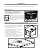
removal From pallet:
• Remove the bricks from the unit before starting.
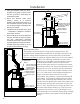
• Remove the two lag bolts (shown in Figure 6) that secure
the unit to the pallet from inside the rebox.
• Remove the shipping bracket at the rear of the unit.
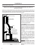
Note: Before the bricks are installed, rivets
(Figure 2) must be placed in the two (2)
holes (shown in Figure 7) in the rebox that
lag bolts came out of. This is done to make
unit burn more efciently.
Figure 7:
Rivet.
Figure 6: Bolts to remove.
15
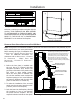
modiFications For installation witH 19
1
/16” (484mm) HigH lintel:
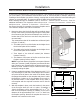
Insert Cabinet Top
Air Deflector
Figure 9: Removing Air Deector onto Cabinet Top.
Figure 8: Removing Cabinet Top from Unit.
The Boston has a factory height of 19
9
/16” (497mm) and
it can be reduced to 19
1
/16” (484mm) by modifying the
unit and the surround panel.
1. Remove the thirteen T-20 screws holding the cabinet
top in place (refer to Figure 8).
2. Remove the cabinet top and ip it onto its top.
3. Remove the Air Deector (shown in Figure 9) by
removing the two (2) T-20 screws.
4. Re-install the cabinet top onto the unit. The screw
holes along the top of the unit should now line up
with the top set of holes on the cabinet top.
Part De scriptio n
SHEET
REV
11/15/2010
1200 Cast Insert
THIS DRAWING IS THE PROPERTY OF SHERWOOD INDUSTRIES LTD. AND MAY NOT BE COPIED, REPRODUCED, OR OTHERWISE DISCLOSED WITHOUT THE PRIOR APPROVAL OF SHERWOOD INDUSTRIES LTD.
DRAWN BY
CHECKE D BY
APPROV AL
Hole Size
+/- .001
ALL DIMENSIONS IN INCHES
TOLERANCE
THREAD S EXTERN AL CL 2A INTERNA L CL 2B
HEAT TR EATMENT
DIMENS IONS APP LY AFTER PLATIN G OR
General
+/- .005
Angles
+/- .5
Hole Pos.
+/- .002
UNLESS OTHERWISE SPECIFIED
MATERI AL
Sherwood Industries Ltd.
HEAT TR EATMENT
SCALE- N OT TO S CALE
FINISH
1 OF 1