www.envirco.
CAUTION AND WARNINGS READ AND SAVE THESE INSTRUCTIONS CAUTION: To reduce the risk of fire, electrical shock or injury to persons, observe the following: A. lnstallation work and electrical wiring must be done by a qualified person(s) in accordance with all applicable codes and standards, including fire-rated construction. B. When cutting or drilling into a wall or ceiling, do not damage electrical wiring or other hidden utilities. C.
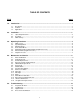
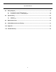
TABLE OF CONTENTS TITLE 1.0. PAGE Introduction ............................................................................................................................... 1 1.1. 1.2. 1.3. 2.0. Installation ................................................................................................................................. 3 2.1. 2.2. 2.3. 3.0. lnitial Set-Up .................................................................................................................................
Operation Manual 6.0. Wiring Diagram ........................................................................................................................ 19 6.1. 6.2. 7.0. Hospi-Gard® lsoClean® Wiring Diagram ............................................................................................19 Hospi-Gard® lsoClean® UV Wiring Diagram......................................................................................20 Specifications ........................................................
HOSPI-GARD® ISOCLEAN® and ISOCLEAN® UV Operation Manual INTRODUCTION 1.0. Introduction 1.1. Description ® ® The Hospi-Gard IsoClean UV is a portable, self-contained high efficiency particulate air (HEPA) ® filtration system with an ultraviolet lamp that helps to disinfect the filter face. The IsoClean UV is designed to easily and economically create a negative pressure isolation room that will meet OSHA and ® CDC TB guidelines.
HOSPI-GARD® ISOCLEAN® and ISOCLEAN® UV Operation Manual 1.3. Applications Hospital Applications Negative Pressure Rooms Emergency Rooms Waiting Rooms Sputum Induction Aerosol Pentamidine Treatment Intensive Care Units Bronchoscopy Rooms Renal Dialysis Rooms Other Applications Clinics Nursing Centers Physician Offices Homeless Shelters Addiction Recovery Centers Correctional Facilities Options ® IsoClean UV with ULPA Filter Upgrade, Part No. 10850-006.
HOSPI-GARD® ISOCLEAN® and ISOCLEAN® UV Operation Manual INSTALLATION 2.0. Installation 2.1. Unpacking Instructions (crated for international) 2.1.1. The Hospi-Gard lsoClean is shipped in an open-framed crate. The module should be inspected for exterior shipping damage immediately upon arrival. If any damage is observed, a claims report should be completed and promptly filed with the responsible carrier. 2.1.2. Uncrate and remove all packing material. Examine the unit for internal damage.
HOSPI-GARD® ISOCLEAN® and ISOCLEAN® UV Operation Manual OPERATING PROCEDURES 3.0. Operating Procedures 3.1. Initial Set-Up 3.1.1. Connect the power cord to a standard 115-Volt, Single Phase, 60 Hertz, or 220-Volt, 50 Hertz, grounded power source. Assure that the circuit is sized to provide sufficient amperage as noted on the Hospi-Gard lsoClean data plate. 3.1.2. Locate the "ON/OFF" switch on the right side of the unit. The switch is a maintain contact rocker type. 3.1.3.
HOSPI-G GARD® ISOCLEAN® andd ISOCLEANN® UV Operration Manua al 3.4. Recircula ation Mode 3.4.1. Th he Hospi-Ga ard lsoClean unit is set a at the factoryy on the 100% % air recircu ulation mode (see 3.2 2). he room air change c rate of the unit w will depend o on both the H Hospi-Gard 3.4.2. Th lso oClean spee ed setting an nd the size o of the room. See Table 1 in the Appe endix for representa ative room aiir changes p per hour (AC CH).
HOSPI-GARD® ISOCLEAN® and ISOCLEAN® UV Operation Manual 3.5. Partial Exhaust/Recirculation Mode NOTE: The lsoClean and lsoClean UV units come with a removable Exhaust Cover Plate and a removable 6-inch (152mm) Duct Collar for attachment to exhaust ducting (not included) to create a negative pressure room. lf the Exhaust Cover Plate is not removed, both the lsoClean and lsoClean UV units will operate in the 100% recirculation mode. 3.5.1.
HOSPI-GARD® ISOCLEAN® and ISOCLEAN® UV Operation Manual 3.6.1.4. The HEPA filtered exhaust air can now be vented to the outside or returned to the main HVAC system2. lf the unit is ducted to an exhaust duct rather than directly to the outside, it must be verified that the exhaust duct is capable of handling the exhaust air expelled by the unit. 3.7.
HOSPI-GARD® ISOCLEAN® and ISOCLEAN® UV Operation Manual 3.7.1.2. lf an exhaust volume greater than 300 CFM (510 m3/h) is required to create a negative pressure room, the optional 8-inch (203.2 mm) 100% exhaust collar (Part No. 11055) should be used as described in Section 3.6. 3.7.1.3. The attachment of ductwork to the exhaust port decreases the air volume exhausted through the port. The magnitude of the decrease varies depending on the length and type of duct as we as its configuration.
HOSPI-G GARD® ISOCLEAN® andd ISOCLEANN® UV Operration Manua al MAIINTENAN NCE AND SERVICE E 4 4.0. Maintenance e and Serrvice 4.1. Parts Ide entification 4.1.1.
HOSPI-G GARD® ISOCLEAN® andd ISOCLEANN® UV Operration Manua al 4.1.2.
HOSPI-GARD® ISOCLEAN® and ISOCLEAN® UV Operation Manual CAUTION: Proper protective equipment and measures must be used at all times during unit cleaning and maintenance. Check with your Safety Office to assure the cleaning solutions, protective equipment (disposable hospital gown, HEPA respirator, protective gloves) and protocols followed comply with your facility’s and CDC guidelines. CAUTION: Disconnect the unit from the electrical power source before attempting service.
HOSPI-GARD® ISOCLEAN® and ISOCLEAN® UV Operation Manual CAUTION: 4.4. Appropriate decontamination procedures (see Section 4.15 must be followed prior to removal of the access panels to replace the HEPA filter or other parts. Contact your Safety Office to assure it conforms to your facility’s protocol. Removal of Front and Rear Panels 4.4.1. Remove the front access panel by taking off the screw covers and removing the four (4) screws. The front panel may now be lifted off. 4.4.2.
HOSPI-GARD® ISOCLEAN® and ISOCLEAN® UV Operation Manual 4.5.5. Remove the six (6) bolts and clamps holding the HEPA filter. Slip a plastic biohazard bag over the filter from the top down. Tilt the top of the filter outward and wrap the bag over the bottom of the HEPA filter. Seal the bag to for containment. NOTE: lt may be necessary to use two (2) biohazard bags to fully contain the filter. 4.5.6. Remove the new HEPA filter from its container and install it in the reverse order of removal.
HOSPI-GARD® ISOCLEAN® and ISOCLEAN® UV Operation Manual 4.10. 4.11. 4.12. Capacitor 4.10.1. With the back panel removed, remove one screw from capacitor strap. 4.10.2. Slide capacitor out. 4.10.3. Remove the rubber boot and disconnect wires. 4.10.4. Replace with the new capacitor, following the steps above in reverse order. Pilot Light 4.11.1 With the back panel removed, disconnect the 3-pin connector and push out pilot light from the inside of the unit. 4.11.
HOSPI-GARD® ISOCLEAN® and ISOCLEAN® UV Operation Manual 4.15. Unit Decontamination NOTE: Use proper protocol, gowning and protective measures during unit decontamination. Should decontamination of the unit be required, the following is an adaptation by Annex G. of the Recommended Microbiological Decontamination Procedure from NSF 49, June 2008. Confirm with appropriate Biosafety and lndustrial Safety Professionals that the procedures meet your facility's guidelines. 4.15.1.
HOSPI-GARD® ISOCLEAN® and ISOCLEAN® UV Operation Manual 4.15.1.8. The temperature should be 21.1° C (70° F) or higher with a humidity level between 60% to 85%. Use the hot plate to heat the beaker of water until the desired temperature and humidity are achieved. Disconnect the hot plate. 4.15.1.9. Seal the film over the remaining opening of the intake grille space. Carefully seal around the power cord extending from the electric frying pan so that formaldehyde gas will not leak out. 4.15.1.10.
HOSPI-GARD® ISOCLEAN® and ISOCLEAN® UV Operation Manual 4.16. UV Light Tube Replacement 4.16.1. The expected life of the UV light tube is nine (9) months to one (1) year depending on the environment and prefilter maintenance schedule. 4.16.2. Remove the five (5) screws on the left hand UV containment baffle or the five (5) screws on the right hand containment baffle and remove the baffle assembly. 4.16.3.
HOSPI-GARD® ISOCLEAN® and ISOCLEAN® UV Operation Manual TROUBLESHOOTING 5.0. Troubleshooting NOTE: Before attempting to service and repair the unit, use proper protocol and follow appropriate decontamination procedures described in the following sections: Section 4.2 Cleaning the Unit Section 4.3 Prefilter Replacement Section 4.14 Relocating a Contaminated Unit Section 4.15 Unit Decontamination 5.1. Inoperative Air Flow 5.1.1.
HOSPI-GARD® ISOCLEAN® and ISOCLEAN® UV Operation Manual WIRING DIAGRAM 6.0. Wiring Diagram 6.1.
HOSPI-GARD® ISOCLEAN® and ISOCLEAN® UV Operation Manual SPECIFICATIONS 7.0. Specifications 7.1. 7.2. IsoClean (10850/10921) Dimensions: 62.25 H x 23.66 W x 15.75 D (in.) 1581 H x 601 W x 400 D (mm) Weight: 250 lbs. (113 kg) ship weight Power Requirements: 6.9 A at 115 V, 60 Hz, Single Phase 3.5 A at 208-230 V, 60 Hz, Single Phase Average Airflow: 560 CFM (951 m3/hr) on Low ±10% 690 CFM (1172 m3/hr) on Medium ±10 800 CFM (1359 m3/hr) on High ±10 HEPA Filter Media: 99.99% at 0.
HOSPI-GARD® ISOCLEAN® and ISOCLEAN® UV Operation Manual REPLACEMENT PARTS 8.0. Replacement Parts 8.1. IsoClean (10850, 115V / 10921, 220V) Part No. 62954 63093 24000 24000-002 62964 63270 62944 63042-008 63042-004 61807 60078 66354 63027 61400 90833 69391-001 62973 62974 23877 37454 Part No.
HOSPI-GARD® ISOCLEAN® and ISOCLEAN® UV Operation Manual 8.2. IsoClean UV (10850-005, 115V / 10921-004, 220V) Part No. 62954 63093 24000 24000-002 62964 62978 62944 63042-008 63093-008 61807 60078 66354 63027 61400 63352 69391-001 62973 62974 23877-003 37454-002 60265 24392-001 Part No.
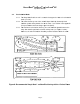
HOSPI-G GARD® ISOCLEAN® andd ISOCLEANN® UV Operration Manua al TE ESTING 9 9.0. Airfllow Meas surementt and Tes sting 1522.4mm 152.4mm 76.2mm 50.8mm 50.8mm 50.
HOSPI-GARD® ISOCLEAN® and ISOCLEAN® UV Operation Manual APPENDIX 10.0.
HOSPI-GARD® ISOCLEAN® and ISOCLEAN® UV Operation Manual LIMITED WARRANTY 11.0. Limited Warranty a)Unless otherwise set forth in the Sales Confirmation, Seller warrants to Buyer, for a period of twelve (12) months following the date of delivery to the Delivery Location (the “Warranty Period”), that the Goods will be free from defects in material and workmanship.
HOSPI-GARD® ISOCLEAN® and ISOCLEAN® UV Operation Manual Envirco USA 101 McNeill Road Sanford, NC 27330, USA Tel: 919.775.2201 Toll Free: 800.884.0002 Fax:800.458.2379 www.envirco.com email: info@envirco.com European Sales The Cavendish Centre Winnall Close Winchester, Hampshire, S023 OLB, UK Tel:+44(0)1962.840465 Fax:+44(0)1962.828619 www.trion.co.uk email: TrionEMEAService@airsysco.com Asian Sales and Manufacturing Building #1 200 Middle Suhong Road Suzhou, Jiangsu PRC 215021 Tel: +86.512.