
Owner manual

guides.
(f) Press the small column head on glass holder, get the wire rope out and remove the glass
slow
ly.
(g) Loosen the bolt which holds the bottomfront board an
d remove the bottomfront board.
(h) Loosen four bolts which holds blower base, di
sconnect the wires and take out of blower
assembly.
(i)Loosen the fixing blower bolt and remove the blower.
(j)Fix the new blower on the blower bracket.
(k)Replace the blower assembly back in reverse steps and tighten bolt.
(l) Seal the connection between blower outlet and air path.
(m)Install the bottom front panel.
(n)Raise the glass and press the small column head on glass folder
, insert the wire rope; the
glass door height should be the same beforedisassembly.
(o)Install with glass track and boards.
(p)Put down the operational panel.
(q)Reset the inflow velocity and exhaust velocity according to
Appendix 1.
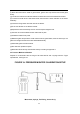
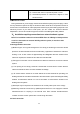
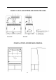
5.2 Pressure Monitor Calibration
Prepare for a barometer with the range of at le
ast 250 Pa and a syringe with the T-type
injected tube, see Figure 10.
FIGURE 10: PRESSURE MONITOR CALIBRATION SETUP
22
Manometer
, Syringe, Tee Fitting, Sensor Ass’y.