4’Biological Safety Cabinet Model Number 11228-001 User Manual Envirco 101 McNeill Rd.
Catalog 4 I、Introduction 1.1 Specifications 5 6 II、Installation 2.1 Position 2.2 Disassembly and handling 2.3 Assembly and installation 2.4 Check?? 6 6 6 7 9 III、Adjustments and testing 3.1 Adjustments on site 3.2 Tests and standards 3.2.1 Filter leakage test 3.2.2 Air adjustment of opening of work area 3.2.3 Downflow air velocity 3.2.4 Pressure test 3.3 Sterilization 9 9 9 9 10 10 10 15 IV、USE AND MAINTENANCE 4.1 General operatingguidelines 4.1.1 Description: 4.1.2 Typical uses 4.1.
5.2 Pressure monitor calibration 5.3 Major parts list 5.4 Fault finding hints 5.5 Attention to maintenance 18 23 19 21 VI、Installations requiring connection to external exhaust systemError! Bookmark not defined. 6.1 Canopy/thimble connection 6.2 Hard connection 6.3 IFlow alarm monitoring system instructions VII 、Label instructions 25 25 26 27 Error! Bookmark not defined. Error! Bookmark not defined. Error! Bookmark not defined.
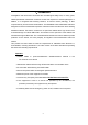
I、Introduction Investigators and technicians concerned with microbiological safety have, for many years, utilized specialized containment enclosures to limit their exposure to harmful pathogens. In addition, it is recognized that exacting research, as well as routine pathology, is often compromised by environmental contamination. The ENVIRCO Class II Biohazard Cabinet is designed to limit the contamination exposure of both the worker and the work when handling biohazard material.
Technical Specifications Model: 11228 -001 Nominal Size: 4Ft.(1.2 meters) Internal Dimensions: (WxDxH): 55.9″x 33.4″x 85.8″ (1421 x 850 x 2180mm) Internal Size: (W x D x H): 48″x 26.1″x25.6″ (1220 x 665 x 650 mm) Average Airflow Velocity: o Inflow:105fpm (0.53±0.015m/s) o Downflow:66fpm (0.33±0.015m/s) Airflow Volume: o Inflow: 275cfm (465m³/h) o Downflow67%: 571cfm (956 m³/h) Exhaust, 33%: 275cfm (465 m³/h) HEPA filter efficiency: >99.99% for particle size above 0.
Power supply: AC 120V±10%, 60Hz ±1Hz Serial number is on cabinet; see operational board mark. II、Installation 2.1Position The Biological safety cabinet should be positioned in an airflow-protected zone in order to prevent the airflow from being adversely affected. This can be caused by ventilation systems,air-conditioning or personnel movement.
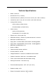
2.3 Assembly and install 1) Assemble the under-frame, see installation Figure 1. FIGURE 1: BASE FRAME ASSEMBLY 1. 2. 3. 4. 5. 6.
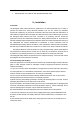
2) Unload the two side panels see Figure 2. 3) Place cabinet onto under-frame and secure with bolts. Bolts are in the cabinet work zone bag.Make the connection between the under frame and cabinet body (sees Figure 3), and then mount side panels; FIGURE 3: CONNECTION OF BASE AND CABINET BODY 1. 2.
3. 4. 5. LEFT PANEL M10 BOLT BASE FRAME 4) Adjust under-frame and level the working surface to ensure the maximum stability on floor. 5) Remove the internal packing materials, empty all parts and clean all debris from inside of the cabinet Note: Any residual debris may lead to damage to the HEPA filters and fan. 6) Check packing list to ensure that all materials and accessories are included.
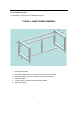
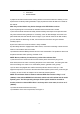
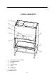
FIGURE 4: MAIN PARTS 1. Exhaust filter protector hood 2. Operational board 3. UV light 4. Control panel 5. Light 6. Power lock 7. Base frame 8.
2.4 Check 1) Connect the biological safety cabinet’s dedicated power line to power outlet on a 120V power source, with a total power of 20 amps. The biological safety cabinet must be the only equipment on the circuit; see the electrical equipment requirements data on the cover. 2) Turn the key on the front panel and press the power button located on the control panel. There will be a delay on the fan in order to achieve the required speed.
III. Adjustments and Testing 3.1 Adjust on site Before packing and transport, this safety cabinet has been tested and confirmed in our factory; however, another test after installation must be performed. Only qualified personnel can adjust this device and in order to ensure the accuracy of the on-site testing, this test equipment must be calibrated. If you cannot implement this operation, please contact ENVIRCO to provide a local on-site testing services company.
APPENDIX 1 DOWNFLOW/HAND INTAKE SETTINGS BIOHAZARD CABINETS-Class II INFLOW MEASUREMENT USING THE THERMOANEMOMETER METHOD MODEL CABINET TYPE 11228 BBC 86 A2 CALCULATED HAND INTAKE HIGHEST READING DOWNFLOW AND LOWEST VELOCITY 0.505-0.555m/s READING 0.305 - 0.355m/s ±20% OF AVERAGE To set the air velocity of the opening work area correctly, we emphasize again that only qualified persons using calibrated equipment may carry out the adjustments.
-------Prior to initiating a totally different work procedure -------When the safety office or safety committee requested NOTE: Only the safety office and the safety committee can determine the correct sterilization procedure. For the convenience of the vapor sterilization, the following cabinet size is available (see chart 7): (Chart 7) MODEL 11228-001 OVERALL SIZE WORKING AREA SIZE Weight LxWxH Inch (mm) LxWxH Inch (mm) Lbs (Kg) 55.59 x 33.46 x 85.82 (1412 X 850 X 2180) 85.82 x 26.18 x 25.
A service record card is permanently attached to the front of the cabinet. An Authorized Service Contractor will record service functions and validate the card upon completion of certification. IV、USE AND MAINTENANCE 4.1 General operation rules 4.1.1 Description: The Biosafety Cabinet should conform to the standard of the American NSF/ANS149-2004and A/B3, an earlier edition. The equipment provides the following three functions: 1.
4.1.3 The air filter system Figure 7 is the equipment’s air flow pattern and the protection zone. The air filter system is the main system to guarantee the equipment’s performance. It consists of a blower, wind pipe, supply filter and exhaust filter. The air filter system’s main function is to produce clean air for the work zone. The average vertical down flow velocity of the clean air in the work zone can reach 0.33fpm +-0.015m/s, while cleaning the exhausted air and preventing environmental pollution. 4.
4.1.5 Digital control circuit (a) The EnvircoBiosafety Cabinet has utilized the latest microprocessor control technology to control and inspect the Biosafety’s Cabinet’s function. It is simple to operate and is user friendly while providing a high degree of reliability for diagnostic functions. (b) Connect the cabinet to the recommended electrical outlet. (c) Turnthe keyclockwise to power the equipment. The display will illuminate, then go dark and repeat three times.
(m) Before calling for service, unplug the cabinet from the wall, wait for 2 minutes, then plug and try restarting the motor. If motor start-up fails, call Envirco for service. 4.1.6 Differential pressure indication Differential pressure indication refers to the pressure difference across the filter. The value is enhanced when the filter loading is increased. The reading is exclusive for each combination of safety cabinet and filter that corresponds to the previous readings of the same cabinet.
Materials Recommended cleaning method Stainless Steel (a) Wipe the entire surface with a soft paper towel soaked in a concentrated soap solution such as SWIPE, MR, CLEAN, etc. Then quickly wipe over with another cloth or towel soaked in clean hot or warm water. The surface will foam but immediately wipe over again with a dry cloth or towel. The surface will rapidly dry with a clean, smear-free appearance. (b)For stained or marked work surface, sinks, etc.
V、SERVICE AND COMPONENTS 5.1 Main components replacement All the components need replacement (except for the control panel, see 5.1.4, installed on the top of the work area). Access to this area is via the removable front panel. Unqualified persons are not permitted to perform the maintenance. It is a necessity that the safety cabinet be sterilized after the front panel has been opened. 5.1.
(f) Remove screws to the front under panel. Remove the front under panel. (g) Remove the four screws under the air screen and take off the air screen. (h) Loosen the screws for the filter and remove the supply filter. (i) Place the screws and the parts aside and install the new HEPA filter. Exhaust filter (k) To the right of the motor there is a spring. Release the self-tapping screw on the spring and take off tubular motor. (l) Remove the screws fixed on the front panel and remove the front panel.
guides. (f) Press the small column head on glass holder, get the wire rope out and remove the glass slowly. (g) Loosen the bolt which holds the bottomfront board and remove the bottomfront board. (h) Loosen four bolts which holds blower base, disconnect the wires and take out of blower assembly. (i)Loosen the fixing blower bolt and remove the blower. (j)Fix the new blower on the blower bracket. (k)Replace the blower assembly back in reverse steps and tighten bolt.
Exhaust filters from top to bottom pressure calibration (a) Open the front operational panel, unplug the trachea from the pressure sensor NPC1A; (b)One of T-type injected tube ends connects with NPC1A and one end with barometer and another with syringes. (c) Press the power button and select exhaust pressure on the display. (d) Using syringe pressure control, observe whether the pressure on the screen and the manometer readings is the same.
5.4Fault finding hints Problem The equipment does not function Solution (a) Check power at the electrical outlet into which the equipment is plugged. (b) Checkthe following three fuse tubes on the circuit to determine if they are broken:Zero wire fuse tube F4 12.5A, Fire wire fuse tube F5 12.
No power in internal outlet (c) ”Outlet” button on control board is off. (d) Problem with units on operational panel or wires. (e) Overloaded protection on outlet wire is tripped or fuse has been blown. 5.5Maintenance notes During maintenance, power supply must be turned off before pulling out power plugs. Users are only allowed to replace UV lamp or fluorescent tubes, while other components should not be removed.
Hard connection is only used in special applications with type A2 Biological Safety Cabinets. Should your situation require such a configuration, contact Envirco for information. 6.3 Instructions for flow alarm monitor system Flow alarm monitor system is a pre-programmed, self-contained package that monitors differential static air pressure. The alarm would note when the air pressure is ±20% beyond the normal pressure.
VII、Label instructions 1.
FIGURE 5: CONTROL PANEL 1. Uv–light 11. Display (security stcabinet) 2. Light 12. Remote control receiver 3. Wm (fan) 13. UV work state display 4. Socket 14. Blower display 5. Up (control for glass door) 15. Intake or exhaust air display 6. Down (control for glass door) 16. Socket display 7. E/d (intake and exhaust air changing) 1 7 . Lightdisplay 8. Power 18. Logo(envirco) 9. Display(glass door) 19. Dynamic exhaust air display 10. Display (security stcabinet) 20.
FIGURE 6: MEASUREMENT OF BIOHAZARD CABINET Front View Side View 29
FIGURE 7: AIR FLOW PATTERN AND PROTECTED AREA Front View Side View FIGURE 8: FRONT ACCESS PANEL REMOVAL 30
Front View Side View 31
FIGURE9: GLASS CLIP 32
A B C N 1 14AW G 14AW G 14AW G 2 6. 3A F7 14AW G 14AW G 16AW G F4 12. 5A F5 12. 5A 16AW G 16AW G L 18AW G 18AW G 16AW G 16AW G 18AW G 3 F6 125mA 12V 5. 3V 18AW G 4 JK3 20AW G 20AW G 6. 3A F3 +12V 20AW G JK2 20AW G 18AW G 20AW G 24V F2 2. 5A 20AW G JK1 +12V 5 5 20AW G 4 F1 2. 5A 20AW G 33 20AW G JK2 20AW G 20AW G JK1 18AW G 20AW G 3 +12V 20AW G 2 6 6 18AW G 20AW G 20AW G 20AW G 20AW G D 1 20AW G 20AW G 20AW G 20AW G 7 7 +12V 0.
Terms and Conditions . ACCEPTANCE: The acceptance of Buyer’s order is expressly made conditional on Buyer’s assent to the terms and conditions set forth herein, and the Seller identified in the quotation or invoice (as applicable) (“Seller”) agrees to furnish the materials, goods, products and services (collectively “Goods”) covered thereby only upon these Terms and Conditions of Sale.
non-stock products, or special orders, or where manufacturing processes make it difficult to provide the exact quantity specified, Seller reserves the right to under-ship or over-ship and invoice Buyer accordingly. 8.
charges, court costs, and legal or other expenses caused solely by the willful misconduct or negligent misconduct of a Seller Indemnities or otherwise covered by Seller’s obligations under Section 11. 11. INFRINGEMENT: Seller will defend at its own expense any action against Buyer brought by a third party to the extent that the action is based upon a claim that the Goods infringe any U.S.
delays or failures are caused by labor difficulties, Seller shall not be obligated to seek or obtain any settlement which, in Seller’ sole judgment, is not in Seller’ best interest. 16. COMPLIANCE: Each party shall comply with all applicable laws, regulations, and ordinances. Without limiting the foregoing, in no event shall Buyer take any action(s) contrary to the United States export laws and regulations in effect as of the date of shipment of the Goods, including without limitation, diversion of Goods.
101 McNeill Rd., Sanford, NC 27330 www.envirco.com 800.884.