
User's Manual Part 3

T
ECHNICAL
D
OCUMENTATION
P
ROTECTING
P
EOPLE AND
A
SSETS
®
D
ATE
:
27
M
ARCH
2017
|
V
ERSION
:
1.8
51
R
ANGER
®
-
X5
R
ADAR
S
YSTEM
(M
OBILE
)
F
UNCTIONAL
O
VERVIEW AND
T
HEORY OF
O
PERATION
EEC
®
|
C
OMPANY
P
ROPRIETARY
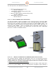
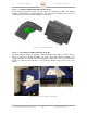
2.1.4.2.2. Horizontal UDC / Transmitter Control (Unit 2 A1 A3 A2 A2)
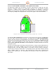
The Ranger-X5 combines the up and down conversion subsystem into a single unit. The UDC
translates information between the intermediate frequency (IF) and X-band operating
frequencies. It utilizes low-noise amplifiers (LNA), RF Amplifiers, IF Amplifiers, a Frequency
Multiplier (on Horizontal Assembly Only), and a Signal Generator (on Horizontal Assembly Only).
The frequency multiplier and signal generator also provide signals for the Vertical Channel.
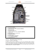
Figure 43. UDC / Transmitter Control Assembly (135898-100) – Horizontal
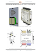
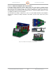
The IQ2-IFD (Unit 2 A1 A3 A1 A1) generates the waveform at the IF frequency of 60MHz that
drives the shape of the waveform for the UDC. The Signal Generator (Unit 2 A1 A3 A2 A2 A6)
provides the RF Frequency and bandwidth of the transmit frequency. The waveform and
frequency mix in the Image Reject mixer before and route to the RF Amplifier (Unit 2 A1 A3 A2
A2 A1). From the RF Amplifier, the RF signal (waveform and frequency) route to the 500W
Power Amplifier (Unit 2 A1 A3 A2 A1) for final amplification and pulse transmission into the
waveguide system.
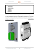
The UDC is a breakthrough in achieving excellent performance of image rejection (without narrow
band filters in the module or multiple conversion states), TR isolation, and phase noise in an
integrated module. This UDC design combines a very simple conversion structure and image-
rejection mixer technology, which achieves strong image rejection performance without onboard
filters or multiple stages of conversion. This technology also helps reduce complexity and
minimize space requirements. The shielded RF enclosure helps to achieve the required level of
TR isolation.