
User's Manual Part 3

T
ECHNICAL
D
OCUMENTATION
P
ROTECTING
P
EOPLE AND
A
SSETS
®
D
ATE
:
27
M
ARCH
2017
|
V
ERSION
:
1.8
49
R
ANGER
®
-
X5
R
ADAR
S
YSTEM
(M
OBILE
)
F
UNCTIONAL
O
VERVIEW AND
T
HEORY OF
O
PERATION
EEC
®
|
C
OMPANY
P
ROPRIETARY
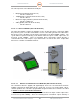
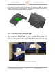
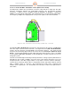
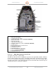
2.1.4.2. Transceiver Assembly (Horizontal) (Unit 2 A1 A3 A2)
The Ranger-X5 transmitter employs an X-band solid-state amplifier as the stable, power device.
Mounted within the saddle of the radar pedestal are the transceiver assembly subsystems. The
SIDPOL® model has two units—one Horizontal and one Vertical (see paragraph Error!
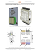
Reference source not found.). The Transceiver Assembly houses:
• 500 Watt Power Amplifier (Unit 2 A1 A2 A1)
• RF Up/Down Converter (UDC) / Transmitter Control Assembly (Unit 2 A1 A2 A2)
• Transceiver Power Supply (Unit 2 A1A2 A3)
• Temperature Humidity Sensor (Unit 2 A1 A2 A4)
• Cross Guide Coupler (Unit 2 A1 A2 DC1)
• 3-Port Circulator (Unit 2 A1 A2 HY1)
• TR Limiter (Unit 2 A2 V1)
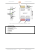
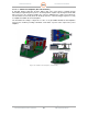
The Transmitter Control Assembly includes an RF coupler that allows the burst signal to pass
through the down-conversion network for sampling by the IQ2-IFD Intermediate Frequency
Digitizer (digital receiver). In order for pulse compression algorithms to approach theoretical
performance, the transmit signal waveforms must be known and used by the matched filter during
the received signal processing stage.
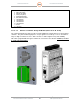
The Power Amplifier is a compact 500W solid-state power amplifier (SSPA) housed within the
Transmitter Assembly. The Transmitter Control Assembly incorporates other radar front-end
components (LNA, RF Amplifier, Signal Generator). Utilizing pulse widths of up to 100µs, the
Transceiver Assembly allows the Ranger-X5 Radar to achieve sensitivity levels comparable to
that of a 250kW transmitter with a 1µs pulse (assuming 100:1 pulse compression ratio).
Figure 41. Horizontal Transceiver Assembly (135895-100)