
User's Manual Part 3


T
ECHNICAL
D
OCUMENTATION
P
ROTECTING
P
EOPLE AND
A
SSETS
®
D
ATE
:
27
M
ARCH
2017
|
V
ERSION
:
1.8
45
R
ANGER
®
-
X5
R
ADAR
S
YSTEM
(M
OBILE
)
F
UNCTIONAL
O
VERVIEW AND
T
HEORY OF
O
PERATION
EEC
®
|
C
OMPANY
P
ROPRIETARY
1.
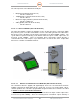
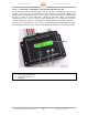
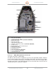
Run / Power LED (Green)
2. Status LED (Yellow)
3. Ethernet Link (Green)
4. Activity LED (Yellow)
5. Default Address Button
6. RJ45 Ethernet Connector
7. Terminal Block 1
8. Terminal Block 2
9. Terminal Block 4
10. Terminal Block 3
11. Ground
12. DC Power
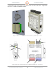
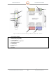
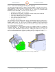
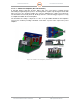
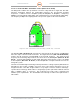
2.1.4.1.2.2. Ethernet 12-Channel Analog I/O Module (Unit 2 A1 A3 A1 A3 A2)
The 12-Channel Analog modules provide an isolated Ethernet network interface for analog input
channels. They have multi-range inputs to accept signals from a variety of sensors and devices.
They are high-resolution, low noise, A/D converters to deliver high accuracy and reliability.
This unit is programmable through a web-based user interface described in Volume 1, Section
4, Vendor Documentation.
Figure 36. Ethernet 12-Channel Analog I/O Module (132839-100) – Position