
User's Manual Part 3

T
ECHNICAL
D
OCUMENTATION
P
ROTECTING
P
EOPLE AND
A
SSETS
®
D
ATE
:
27
M
ARCH
2017
|
V
ERSION
:
1.8
57
R
ANGER
®
-
X5
R
ADAR
S
YSTEM
(M
OBILE
)
F
UNCTIONAL
O
VERVIEW AND
T
HEORY OF
O
PERATION
EEC
®
|
C
OMPANY
P
ROPRIETARY
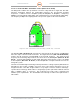
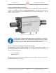
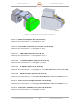
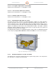
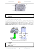
Figure 51. Vertical Transceiver Assembly (135891-100)
2.1.4.3.1. 500W Power Amplifier (Unit 2 A1 A3 A3 A1)
Identical to the Horizontal Unit – see paragraph 2.1.4.2.1.
2.1.4.3.2. Vertical UDC / Transmitter Control (Unit 2 A1 A3 A3 A2)
Identical to the Horizontal Unit - see Paragraph 2.1.4.2.2.
2.1.4.3.2.1. LNA, X-Band (Unit 2 A1 A3 A3 A2 A1)
Identical to the Horizontal Unit – see Paragraph 2.1.4.2.2.1.
2.1.4.3.2.2. Coaxial RF Amplifier (Unit 2 A1 A3 A3 A2 A2)
Identical to the Horizontal Unit - see Paragraph 2.1.4.2.2.2.
2.1.4.3.2.3. IF Amplifier (Unit 2 A1 A3 A3 A2 A3)
Identical to the Horizontal Unit - see Paragraph 2.1.4.2.2.3.Error! Reference source not found.
2.1.4.3.2.4. PIN Diode Limiter (Unit 2 A1 A3 A3 A3 V1)
Identical to the Horizontal Unit - see Paragraph Error! Reference source not found.1.4.2.2.5.
2.1.4.3.3. Transceiver Power Supply Unit (Unit 2 A1 A3 A3 A3)
Identical to the Horizontal Unit - see Paragraph Error! Reference source not found.2.1.4.2.3.
2.1.4.3.4. Temperature / Humidity Sensor (Unit 2 A1 A3 A3 A4)
Identical to the Horizontal Unit - see Paragraph 2.1.4.2.4