
User's Manual Part 3

T
ECHNICAL
D
OCUMENTATION
P
ROTECTING
P
EOPLE AND
A
SSETS
®
D
ATE
:
27
M
ARCH
2017
|
V
ERSION
:
1.8
52
R
ANGER
®
-
X5
R
ADAR
S
YSTEM
(M
OBILE
)
F
UNCTIONAL
O
VERVIEW AND
T
HEORY OF
O
PERATION
EEC
®
|
C
OMPANY
P
ROPRIETARY
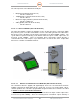
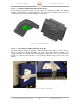
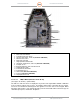
Figure 44. UDC / Transmitter Control (135898-100)
1.
Signal
Generator, LMS
-
103
2. Power Divider, RFLT3WG18G
3. Coaxial RF Amplifier, ZVA-183X-S+
4. Transceiver Power Supply, 134728-100 (NOT AN RF COMPONENT)
5. PIN Diode Limiter, LP7012
6. X-Band LNA, CA910-259L
7. Image Reject Mixer, IRM0812LC2B-1
8. Temperature / Humidity Sensor, 134951-100 (NOT AN RF COMPONENT)
9. IF Amplifier, ZJL-7G
10. Narrow Bandwidth Cavity Filters, 3C60-9275/U10-0/0
11. Variable Attenuator, ARM-1
12. Coaxial Attenuator, BW-S40W2
13. Coaxial Switch, S2X1-1-5
14. Interlock Switch (NOT AN RF COMPONENT)
15. Cooling Fan (NOT AN RF COMPONENT)
16. 2-Way Splitter, ZFSC-2-10G
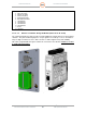
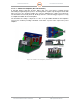
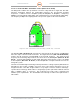
2.1.4.2.2.1. LNA, X-Band (Unit 2 A1 A3 A2 A2 A1)
(See Figure 44, Point 6) - (CA910-259L)
The LNA is a solid-state device to amplify the very weak return signal with a minimal contribution
to the overall noise figure of the receiver. The primary characteristic of an LNA is the noise figure,
a measure of how much the LNA degrades the signal-to-noise ratio of the received signal. Other
important characteristics of the LNA are linearity (measured in P1dB or third order intercept), the
survivable input power, and the DC dissipation.