
User's Manual Part 2

T
ECHNICAL
D
OCUMENTATION
P
ROTECTING
P
EOPLE AND
A
SSETS
®
D
ATE
:
22
M
ARCH
2017
|
V
ERSION
:
1.4
76
R
ANGER
-X5
R
ADAR
S
YSTEM
T
ROUBLESHOOTING
,
M
AINTENANCE
,
AND
C
ALIBRATION
EEC
®
|
C
OMPANY
P
ROPRIETARY
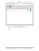
5.2. Transmitter Verification Procedures
5.2.1. Transmitter Control and Indicator Test
These tests verify the operation of the transmitter-receiver controls and indicators.
1. Set point of control to REMOTE. With radar control at the operator workstation, use the
mouse to verify the following functions operate correctly:
• Radar Transmitter Power ON/OFF
• Radiate Mode ON/OFF
• Servo Power ON/OFF
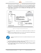
2. It is required that user intervention be required after and emergency system shutdown.
The following steps will demonstrate the procedure enclosure box.
3. Place the system in a normal operating mode.
4. Activate the Emergency Stop switch located on the pedestal.
5. Verify removal of power to the pedestal.
6. Rotate the Emergency Stop switch in the direction of the indicator arrows and verify the
E-Stop return the normal operating position and the restoration of system power after
pressing and holding the E-Reset button for 10 seconds.
7. Verify that the system automatically returns to operation.
Pass
Fail
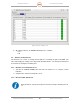
5.2.2. Transmitter Control Panel Switches and Indicators Test
These tests verify the operation of the transmitter control panel switches and indicators.
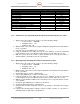
1. Using Table 12 as a reference verify each switch and indicator functions as described.
Switch/Indicator
Function
Pass/Fail/NA
Comments
Emergency Stop
De
-
activates pedestal
power immediately
when depressed.
Pass Fail NA
Table 12 Transmitter Control Panel Switches and Indicators Reference Table