
User's Manual Part 2

T
ECHNICAL
D
OCUMENTATION
P
ROTECTING
P
EOPLE AND
A
SSETS
®
D
ATE
:
22
M
ARCH
2017
|
V
ERSION
:
1.4
57
R
ANGER
-X5
R
ADAR
S
YSTEM
T
ROUBLESHOOTING
,
M
AINTENANCE
,
AND
C
ALIBRATION
EEC
®
|
C
OMPANY
P
ROPRIETARY
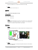
Open the Pedestal Plate Enclosure Assembly using the latches and swing the lid out of
the way.
2. Step 2:
Disconnect all connectors to the Servo Amplifier including Power, Ethernet, and
Command and Control. Refer to Volume 2, Section 1, Paragraph 2.1.5.2. for a
complete description of all connectors.
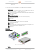
3. Step 3:
Disconnect the four (4) retaining screws using a Philips screwdriver that mount the
Servo Amplifier to the Pedestal Plate Enclosure Assembly. See Figure 16, Red Circles.
4. Step 4:
Reinstall in reverse order of Steps 1-3.
Calibration and Verification:
See Paragraph 5.3.1, 5.3.2, 5.3.3, 5.3.4, & 5.3.5.
2.1.5.3. Fiber Optic Coupler (Unit 2 A1 A5 A3)
Troubleshooting:
SD-135896-100 Sheet 3 of 3
EEC-135886-100 Sheet 1 of 5
Sheet 2 of 5
Sheet 3 of 5
If the Fiber-Optic communications is not functioning properly, check an open port on the coupler.
If the port is malfunctioning, replace the Coupler.
Maintenance:
Disconnect the Coupler from the mount using the single mounting screw. Disconnect the cables.
Reinstall in reverse order.
Calibration:
None.
2.1.5.4. Aquarian Servo Controller PCA (Unit 2 A1 A5 A4)
Troubleshooting:
SD-135886-100 Sheet 1 of 3