
User's Manual Part 1

T
ECHNICAL
D
OCUMENTATION
P
ROTECTING
P
EOPLE AND
A
SSETS
®
D
ATE
:
27
M
ARCH
2017
|
V
ERSION
:
1.8
23
R
ANGER
®
-
X5
R
ADAR
S
YSTEM
(M
OBILE
)
F
UNCTIONAL
O
VERVIEW AND
T
HEORY OF
O
PERATION
EEC
®
|
C
OMPANY
P
ROPRIETARY
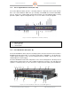
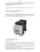
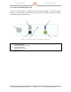
Figure 15. Safety Relay (RT6-24VDC)
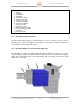
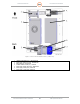
1.1.10.4. 24VDC Power Supply (Unit 1 A10 PS1)
(See Figure 13, Point 6)
The 24VDC Power Supply (PS1) is outside of the control of the Emergency Stop System. PS1
provides power to the Safety Replay (RT6), which in turn, controls the AC power supply to the
other DC Power Supplies (PS2, PS3, and PS4).
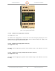
1.1.10.5. 48VDC Power Supply (Unit 1 A10, PS2)
(See Figure 13, Point 5)
The 48VDC Power Supply (PS2) provides all the 48VDC voltage for the Antenna / Pedestal
Assembly.
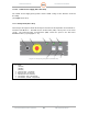
1.1.10.6. 24VDC Power Supply, 600W, 27A Peak (Unit 1 A10 PS3)
(See Figure 13, Point 2)
The 24VDC Power Supply (PS3) provides all the 24VDC voltage for the Antenna / Pedestal
Assembly.