
User's Manual Part 2


T
ECHNICAL
D
OCUMENTATION
P
ROTECTING
P
EOPLE AND
A
SSETS
®
D
ATE
:
27
M
ARCH
2017
|
V
ERSION
:
1.8
42
R
ANGER
®
-
X5
R
ADAR
S
YSTEM
(M
OBILE
)
F
UNCTIONAL
O
VERVIEW AND
T
HEORY OF
O
PERATION
EEC
®
|
C
OMPANY
P
ROPRIETARY
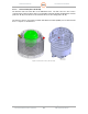
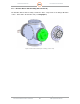
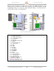
This processing can include pulse compression as an option. The digital IF signals pass to the
IQ2-DSP unit via a 2.5 Gbits/sec optical link and command/control/status information is through
a Gigabit Ethernet link. The unit has nine fully programmable triggers, serial angle input ports,
and other I/O ports that for special applications.
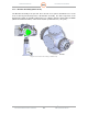
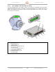
Figure 32. IQ2-IFD (134066-101)
1.
J18
–
External Clock M
onitor
2. J19 – Reference Clock Test Point
3. J10 – Reference Clock Monitor
4. J15 – Trigger Generator Test Point
5. P10 – 12 VDC Power
6. J13, Fiber Optic
7. J17 – PCIe (not used in SDP system)
8. J8 – Ethernet
9. J9 – IRX Connector (not used)
10. J12 – Antenna Position
11. P5 – Sync
12. P3 – Trigger
13. P4 – GPIO
14. J14 Fiber Optic
15. J1 – RX Channel 1
16. J2 – RX Channel 2
17. J3 – RX Channel 3
18. J4 – RX Chanel 4
19. J5 – Burst
20. J6 – Waveform Generator
21. J77 – Waveform Generator (2)
22. J11 – Clock Reference In
23. J16 – RS232 / I2C / SAFC
24. Directional Coupler, ZFDC-20-4-S+
25. IQ2 PSU PCA – 134862-100
RED OUTLINE - 10dB Attenuator, VAT-10
BLUE OUTLINE - 5dB Attenuator, VAT-5