
User's Manual Part 2


T
ECHNICAL
D
OCUMENTATION
P
ROTECTING
P
EOPLE AND
A
SSETS
®
D
ATE
:
27
M
ARCH
2017
|
V
ERSION
:
1.8
41
R
ANGER
®
-
X5
R
ADAR
S
YSTEM
(M
OBILE
)
F
UNCTIONAL
O
VERVIEW AND
T
HEORY OF
O
PERATION
EEC
®
|
C
OMPANY
P
ROPRIETARY
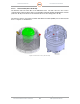
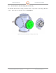
2.1.4. Payload Support Assembly (Unit 2 A1 A3)
The Payload Support Assembly (Unit 2 A1 A3) houses the entire transmitter and receiver system
in the Plenum Assembly (Unit 2 A1 A3 A1), the Transceiver Assemblies – Horizontal (Unit 2 A1
A3 A2) and Vertical (Unit 2 A1 A3 A3), and the Fluid Pump Assembly (Unit 2 A1 A3 A4).
Figure 30. Payload Support Assembly (135953-100)
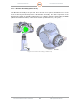
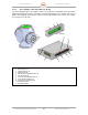
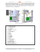
2.1.4.1. Plenum Assembly (Unit 2 A1 A3 A1)
The Plenum Assembly (aka the Saddle) houses the IQ2 IFD, the I/O Control Modules, the Cold
Plate, the 8-Port Ethernet Switch, and the Peltier Temperature Controllers for the Cold Plate and
the Fluid Pump Assembly.
Figure 31. Plenum Assembly (135540-100)
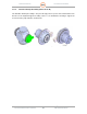
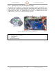
2.1.4.1.1. IQ2 Intermediate Frequency Digitizer Assembly (Unit 2 A1 A3 A1 A1)
The IQ2-IFD receives the horizontal and vertical receive IF from the Horizontal UDC (Unit 2 A1
A3 A2 A2) and Vertical UDC (Unit 2 A1 A3 A3 A2). The IQ2-IFD digitizes the received IF and
outputs “I and Q” serial data in digital format. The data output connects to the IQ2-DSP via a
fiber-optic cable and the fiber-optic rotary joint.
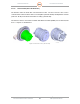
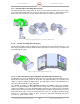
The IQ2-IFD Assembly (see Error! Reference source not found.) extracts the maximum
amount of useable information from reflected radar energy. There are five 60 MHz IF channels
sampled at >76 MHz. Four of the IQ2-IFD 60 MHz IF channels (two channels for the horizontally
polarized signal and two channels for the vertically polarized signal in dual polarization systems)
include wide-band down-converters to base-band for Receiver use. The fifth IF channel normally
functions as a Transmitter sample (IF burst) channel for Transmitter amplitude and phase
correction on a pulse-by-pulse basis.