
User's Manual Part 1


DATE: 22 MARCH 2017 | VERSION: 1.4
IV
RANGER-X5 RADAR SYSTEM
T
ROUBLESHOOTING
,
M
AINTENANCE
,
AND
C
ALIBRATION
EEC
®
|
C
OMPANY
P
ROPRIETARY
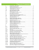
TABLE OF FIGURES
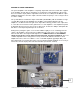
Figure 1. Outdoor Control Cabinet ....................................................................................................................................... 3
Figure 2. 1.8 Meter Ranger-X5 Variant .............................................................................................................................. 4
Figure 3. Signal Processor Status Summary Tab ......................................................................................................... 10
Figure 4. Signal Processor Status DST Voltages Tab ................................................................................................. 11
Figure 5. Signal Processor Status DST Temperature Tab ......................................................................................... 11
Figure 6. KVM Connections ................................................................................................................................................. 12
Figure 7. EDGE Wrokstation ................................................................................................................................................ 14
Figure 8. 24VDC Power Supply .......................................................................................................................................... 18
Figure 9. Servo Amplifier Removal .................................................................................................................................... 29
Figure 10. Regeneration Clamp .......................................................................................................................................... 32
Figure 11. Plenum Assembly – Cover Retaining Screws and Latches .................................................................. 34
Figure 12. Plenum Assembly – IQ2-IFD Retaining Bracket ....................................................................................... 35
Figure 13. Ethernet Switch Retaining Brackets ............................................................................................................. 43
Figure 14. Temperature Controller Retaining Screws ................................................................................................. 44
Figure 15. UDC / Transmitter Control Signal Flow........................................................................................................ 48
Figure 16. Servo Amplifier Removal .................................................................................................................................. 56
Figure 17. Regeneration Clamp .......................................................................................................................................... 59
Figure 18. Test Setup for Peak Power Measurements ............................................................................................... 72
Figure 19 UST Temperature Tab ....................................................................................................................................... 77
Figure 20 UST Voltages Tab................................................................................................................................................ 78
Figure 21 DST Temperatures Tab ..................................................................................................................................... 79
Figure 22 DST Voltages Tab................................................................................................................................................ 80
Figure 23. Typical Calibration Test Results Screenshot (LDR > 100dB) .............................................................. 85
TABLE OF TABLES
Table 1. Discrete (Digital) I/O Module ............................................................................................................................... 37
Table 2. Analog I/O Map ........................................................................................................................................................ 39
Table 3. Transceiver and UDC Voltages .......................................................................................................................... 45
Table 4. UDC / TX Control Power Distribution ............................................................................................................... 47
Table 5 Power Sensor Worksheet...................................................................................................................................... 71
Table 6 Typical power Sensor Specifications ................................................................................................................. 71
Table 7 Peak Power Calculation using Duty Cycle Correction ................................................................................. 73
Table 8 Example of Peak Power Calculation.................................................................................................................. 73
Table 9. Peak Power Test Results ..................................................................................................................................... 74
Table 10. Velocity Scale and Nyquist Interval ................................................................................................................ 75
Table 11. Data Output Verification ..................................................................................................................................... 75
Table 12 Transmitter Control Panel Switches and Indicators Reference Table .................................................. 76
Table 13. Receiver Noise Figure and Dynamic Range Test Results ...................................................................... 84