
User's Manual Part 1


T
ECHNICAL
D
OCUMENTATION
P
ROTECTING
P
EOPLE AND
A
SSETS
®
D
ATE
:
22
M
ARCH
2017
|
V
ERSION
:
1.4
39
R
ANGER
-X5
R
ADAR
S
YSTEM
T
ROUBLESHOOTING
,
M
AINTENANCE
,
AND
C
ALIBRATION
EEC
®
|
C
OMPANY
P
ROPRIETARY
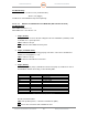
6. Step 3 (Status):
If the unit has power (Step 1) and Ethernet Connection (Step 2), troubleshoot each of
the individual channels and relays per the following table:
Terminal Block
Pin
Status
TB1
11
H Transmitter +5V Monitor
12
H UDC +5V Monitor
13
Return / Ground
14
H Transmitter +12V Monitor
15
H +48V Current
16
Return / Ground
TB2
21
H Temp Sensor
22
H Humidity Sensor
23
Return / Ground
24
V Transmitter +5V Monitor
25
V UDC +5V Monitor
26
Return / Ground
TB4
41
V Transmitter +12V Monitor
42
V +48V Current
43
Return / Ground
44
V Temp
Sensor
45
V Humidity Sensor
46
Return / Ground
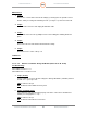
Table 2. Analog I/O Map
Are all connections intact?
YES: If the problem persists, contact the manufacturer (EEC).
NO: Restore the connections and revalidate the tests.
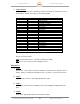
Maintenance:
1. Step 1:
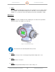
Remove the cover from the Plenum Assembly by releasing the four quick-disconnect
latches and by loosening two Retaining Screws (see Figure 11), then remove the lid.
5. Step 2:
Disconnect all connectors and unplug the Ethernet cable.
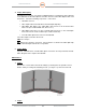
6. Step 3:
Loosen and remove the two (2) Philips head screws holding the retaining bracket in
place..
7. Step 4:
Remove the Analog I/O Unit from the Plenum Assembly.