
User's Manual Part 1


T
ECHNICAL
D
OCUMENTATION
P
ROTECTING
P
EOPLE AND
A
SSETS
®
D
ATE
:
22
M
ARCH
2017
|
V
ERSION
:
1.4
37
R
ANGER
-X5
R
ADAR
S
YSTEM
T
ROUBLESHOOTING
,
M
AINTENANCE
,
AND
C
ALIBRATION
EEC
®
|
C
OMPANY
P
ROPRIETARY
Troubleshooting:
SD-135953-100 or -101 Sheet 3 of 4 (Communication)
Sheet 4 of 4 (Trigger)
Troubleshoot each individual component separately.
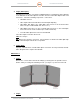
2.1.3.1.2.1. Ethernet 16-Channel Discrete I/O Module (Unit 2 A1 A3 A1 A3 A1)
Troubleshooting:
SD-135964-100 Sheet 1 of 1
SD-135953-100 or 101 Sheet 3 of 4
1. Step 1 (Power):
Using a voltmeter, measure the DC Voltage the Discrete I/O Module (+24VDC) at Pin
31 and Pin 32. Is power present?
YES: Continue to Step 2.
NO: Troubleshoot the 24VDC Power System.
2. Step 2 (Communication):
Is the Ethernet connection working properly? Check the connection to the Ethernet
Switch (See Paragraph 2.1.3.1.4).
YES: Continue to Step 3.
NO: Troubleshoot the Ethernet connection.
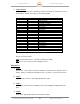
3. Step 3 (Status):
If the unit has power (Step 1) and Ethernet Connection (Step 2), troubleshoot each of
the individual channels and relays per the following table:
Terminal Block
Pin
Status
TB1
11
Aux Power Enable
16
Return / Ground
TB2
21
UDC Power Enable
26
Return / Ground
TB4
43
Trigger Enable (K1)
44
Trigger Enable (K2)
45
Aux Power Enable
42
UDC Power Enable
Table 1. Discrete (Digital) I/O Module
Are all connections intact?
YES: If the problem persists, contact the manufacturer (EEC).
NO: Restore the connections and revalidate the tests.