
User's Manual Part 1


T
ECHNICAL
D
OCUMENTATION
P
ROTECTING
P
EOPLE AND
A
SSETS
®
D
ATE
:
22
M
ARCH
2017
|
V
ERSION
:
1.4
34
R
ANGER
-X5
R
ADAR
S
YSTEM
T
ROUBLESHOOTING
,
M
AINTENANCE
,
AND
C
ALIBRATION
EEC
®
|
C
OMPANY
P
ROPRIETARY
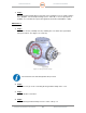
4. Step 4 (Fiber Optic):
If the Ethernet Connection is working, but digitized data is not making it from the IQ2-IFD
to the IQ2-DSP via the Fiber Optic Connection, then check the Fiber Optic Cables and
Connectors. Check the following components / connections:
• IQ2-IFD Connector
• Fiber -Optic Cable from IQ2-IFD to the Fiber-Optic Slip Ring
• Fiber-Optic Slip Ring to the Fiber-Optic Interconnect in the Pedestal Plate
Enclosure (P3 on SD=135886-100, Sheet 3 of 3)
• Fiber-Optic Interconnect on the Pedestal Plate Enclosure to the Fiber-Optic
Interconnect in the Control Cabinet (P3 on SD-135732-100).
• From the Fiber-Optic Interconnect to the IQ2-DSP
Is the Fiber Optic Connection Restored?
YES: Go to Step 5.
NO: Replace the defective connection. If the problem is isolated to the Fiber-Optic Slip
Ring, contact Enterprise Electronics Corporation.
5. Step 5 (Data):
If power, communications, and the Fiber-Optic connections are all operational, the IQ2-
IFD is likely defective. Replace the IQ2-IFD.
Maintenance:
1. Step 1:
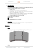
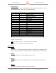
Remove the cover from the Plenum Assembly by releasing the four quick-disconnect
latches and by loosening two Retaining Screws (see Figure 11), then remove the lid.
Figure 11. Plenum Assembly – Cover Retaining Screws and Latches
1. Step 2: