
User's Manual Part 1


T
ECHNICAL
D
OCUMENTATION
P
ROTECTING
P
EOPLE AND
A
SSETS
®
D
ATE
:
22
M
ARCH
2017
|
V
ERSION
:
1.4
33
R
ANGER
-X5
R
ADAR
S
YSTEM
T
ROUBLESHOOTING
,
M
AINTENANCE
,
AND
C
ALIBRATION
EEC
®
|
C
OMPANY
P
ROPRIETARY
Calibration:
None
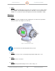
2.1.3. Payload Support Assembly (Unit 2 A1 A3)
2.1.3.1. Plenum Assembly (Unit 2 A1 A3 A1)
2.1.3.1.1. IQ2 Intermediate Frequency Digitizer Assembly (Unit 2 A1 A3 A1 A1)
Troubleshooting:
SD-135953-101 or -101 Sheet 1 of 4 (Power)
Sheet 3 of 4 (Communication)
Sheet 4 of 4 (Trigger)
SD-133066-101 Sheet 1 of 1
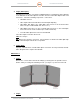
1. Step 1 (Power):
The 24VDC Power supplied to the IQ2 PSU PCA routes from the Slip Ring Assembly to
Terminal Block 1 (TB1) in the Payload Support Assembly on Pins 7 and 8, and from there
to the IQ2 PSU PCA Plug (Pin 1 and 2). Use the appropriate Schematics to trace the
power from the source to the PSU in a logical manner. Is power present at the plug?
YES: Go to Step 2.
NO: Trace the power back to the power supply and restart this troubleshooting
procedure.
2. Step 2 (Power Supply Unit - PSU):
If 24VDC Power is available in Step 1 on the input side of the PSU, check the output side
of the 5VDC power at Pin 5 and 6 on the PSU. Is output power present?
YES: Go to Step 3.
NO: Replace the PSU and restart this troubleshooting procedure.
3. Step 3 (Communication):
Does the IQ2-IFD respond to commands via the Ethernet Connection?
YES: Go to Step 4.
NO: Troubleshoot the Ethernet Connection through:
• Ethernet Switch (Unit 2 A1 A3 A1 A5)
• Slip Ring (Unit 2 A1 A1 A1)
• Azimuth Assembly (Unit 2 A1 A1: SD-135887-100, Sheet 1 of 3)
• Pedestal Plate Enclosure Assembly (Unit 2 A1 A5: SD-135886-100, Sheet 3 of 3)
• Fiber Optic Media Converter (Unit 1 A8)
• 16-Port Gigabit Ethernet Switch (Unit 1 A5).
If the communication connection is restored, continue to Step 4.