
User's Manual Part 1


T
ECHNICAL
D
OCUMENTATION
P
ROTECTING
P
EOPLE AND
A
SSETS
®
D
ATE
:
22
M
ARCH
2017
|
V
ERSION
:
1.4
31
R
ANGER
-X5
R
ADAR
S
YSTEM
T
ROUBLESHOOTING
,
M
AINTENANCE
,
AND
C
ALIBRATION
EEC
®
|
C
OMPANY
P
ROPRIETARY
3. Step 3 (Communication):
Is the Ethernet connector inserted properly?
NO: Reinsert and restart this step.
YES: Go to Step 4.
4. Is the Ethernet Switch (Unit 2 A1 A3 A1 A5) functioning properly (See Paragraph
2.1.3.1.4)
NO: Repair the Ethernet Switch per Paragraph 2.1.3.1.4)
YES: End Process.
Maintenance:
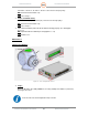
1. Step 1:
Open the Elevation Assembly FRONT Cover using a Philips Screwdriver (12 Screws).
See Figure 9, Point 1.
Do not remove the cover where the Regeneration Clamp is mounted.
2. Step 2:
Disconnect all connectors to the Aquarian Servo Controller including Power, Ethernet,
and Command and Control. Refer to Volume 2, Section 1, Paragraph 2.1.2.4. for a
complete description of all connectors.
3. Step 3:
Loosen and remove the four (4) Philips head screws and standoffs.
4. Step 4:
Remove the Aquarian Servo Controller from the Elevation Assembly.
5. Step 5:
Reinstall in reverse order of Steps 1-4.
Calibration:
None
2.1.2.5. Regeneration Clamp (Unit 2 A1 A2 A5)
Troubleshooting:
SD-134953-100 Sheet 1 of 4