
User's Manual Part 1

RANGER X5 TUNING PROCEDURE
The power amplitude of the amplifier is completely dependent on the level of RF drive supplied
to the amplifier. The RF drive is dependent on several factors. Drive amplitude is affected by
the local oscillator output (which is adjustable in increments of 0.5 dBm), the 60 MHz IF output
amplitude which derives from the output of the IFD, and the frequency to a lesser degree due to
loss in the cabling.
The system will have a minimum output of 500 Watts (56.989 dBm), with an allowable overage
of 0.792 dBm (Total Overage 600Watts (57.781dBm)). The maximum RF drive into the
amplifier is +14 dBm, however the gain of two amps will not always yield the same output. Due
to some minor inconsistencies in the gain and losses of the amplifiers, each amplifier may have
its RF input drive increased or decreased. In other words, we have the ability to manipulate the
RF drive to each amp independently from one another.
During factory testing the gain is set to around 10 dBm roughly to use as a starting point. The
output of the amplifier is measured using a calibrated peak power meter (sensor) during this
time. The RF drive is then adjusted through the use of SMA attenuators on the 60 MHz IF
signal used in the up-convert chain for Input, Horizontal, and Vertical Channels. The local
oscillator amplitude can be changed if necessary, however this will affect the drive to both
amplifiers therefore, the local oscillator is set to a standard amplitude (typically 9 dBm), and
drive adjustments are made by increasing or decreasing the 60 MHz amplitude as necessary to
achieve the desired output power from the transmitters (Horizontal / Vertical).
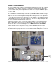
SMA attenuators on the 60 MHz IF signal used in the up-convert chain for Input (3.), Horizontal (1.), and
Vertical (2.) Channels.
1.
2
.
3
.