
User's Manual Part 1

T
ECHNICAL
D
OCUMENTATION
P
ROTECTING
P
EOPLE AND
A
SSETS
®
D
ATE
:
22
M
ARCH
2017
|
V
ERSION
:
1.4
21
R
ANGER
-X5
R
ADAR
S
YSTEM
T
ROUBLESHOOTING
,
M
AINTENANCE
,
AND
C
ALIBRATION
EEC
®
|
C
OMPANY
P
ROPRIETARY
1. Disconnect the terminals / wires from the Contactor.
2. Use a slotted screwdriver to disconnect the Contactor from the DIN rail.
3. Reinstall in reverse order of Steps 1-2.
Calibration:
None
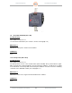
1.11.3. Safety Relay (Unit 1 A13 K2)
Troubleshooting:
SD-134932-101 Sheet 1 of 1
1. Initial Testing:
The Safety Relay receives power from a 24VDC Power Supply (PS1). Is power
present?
NO: Go to Paragraph 1.11.4
YES: Go to Step 2
2. Reset E-Stop
Press the E-Stop Button and then press the E-Stop Reset Button. Is power restored
TO the Contactor (K1). Check the input of the Contractor (K1) at point A1 and A2.
YES: Return to Paragraph 1.11, Troubleshooting, Step 5.
NO: Replace the Safety Relay.
Maintenance:
To replace the Safety Relay:
1. Disconnect the terminals / wires from the Safety Relay.
2. Use a slotted screwdriver to disconnect the Safety Relay from the DIN rail.
3. Reinstall in reverse order of Steps 1-2.
Calibration:
None
1.11.4. 24VDC Power Supply (Unit 1 A13 PS1)
Troubleshooting:
SD-134932-101 Sheet 1 of 1
1. Initial Testing:
Using a voltmeter, measure the voltage of PS1 (Unit 1 13 PS1) to verify proper voltage
output. Check at the output of the power supply. Is it providing 24 VDC?
NO: Verify AC power is present by measuring the input voltage on the TB1-3, 4, & 5 to