
User's Manual Part 1

T
ECHNICAL
D
OCUMENTATION
P
ROTECTING
P
EOPLE AND
A
SSETS
®
D
ATE
:
22
M
ARCH
2017
|
V
ERSION
:
1.4
20
R
ANGER
-X5
R
ADAR
S
YSTEM
T
ROUBLESHOOTING
,
M
AINTENANCE
,
AND
C
ALIBRATION
EEC
®
|
C
OMPANY
P
ROPRIETARY
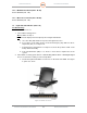
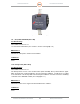
1.11.1. Lightning Protection Module (Unit 1 A13 A1)
Troubleshooting:
SD-135956-100 Sheet 2 of 3
SD-134932-101 Sheet 1 of 1
If the Ranger-X5 has lost communication to the outside WAN, this unit may need to be replaced.
Test this unit by bypassing the connection temporarily.
Maintenance:
To replace the Lightning Protection Module:
1. Unscrew the four screws mounting the system to the DC Power Distribution Plate.
2. Disconnect the ground wires.
3. Disconnect the Ethernet Cables.
4. Reinstall in reverse order of Steps 1-3.
Calibration:
None
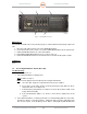
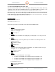
1.11.2. Contactor, 3-Phase, 24VDC (Unit 1 A13 K1)
Troubleshooting:
SD-134932-101 Sheet 1 of 1
The Contactor (K1) is controlled through the Safety Relay (K2).
1. Initial Testing:
If DC power is applied to the Contactor, it closes and allows AC power to flow through
the relay to the other three DC power supplies on the DC Power Distribution Plate (Unit
1 A13). If DC power is removed, the switch opens and removes AC power preventing
the operation of the other DC Power Supplies. Control is through the Safety replay.
Insure DC power is available on A1 and A2 of the Contactor. Is it present?
NO: Reset the E-Stop System and check the output DC power from Point 14 on the
Safety Relay (K2). Is DC power present?
YES: Replace the Contactor (K1).
NO: Go to Paragraph 1.11.3
YES: Return to Paragraph 1.11
Maintenance:
To replace the Contactor: