
User's Manual Part 1

T
ECHNICAL
D
OCUMENTATION
P
ROTECTING
P
EOPLE AND
A
SSETS
®
D
ATE
:
22
M
ARCH
2017
|
V
ERSION
:
1.4
19
R
ANGER
-X5
R
ADAR
S
YSTEM
T
ROUBLESHOOTING
,
M
AINTENANCE
,
AND
C
ALIBRATION
EEC
®
|
C
OMPANY
P
ROPRIETARY
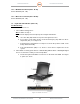
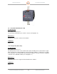
1.11. DC Power Distribution Plate (Unit 1 A13)
The DC Power Distribution Plate control is through the E-Stop Panel (Unit 1 A12). When any
component on the DC Power Distribution Plate is not functioning (with the exception of the
Lightning Protection Module), follow the troubleshooting procedures in this section.
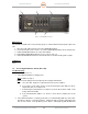
When the operator presses the E-Stop Button, the Safety Relay (K2) removes DC Power from
the Contactor (K1). When the Contactor (K1) is OPEN, AC Power is removed from the main DC
Power Supplies (PS2, PS3, PS4) which provide DC power to the Pedestal (Unit 2). Should the
24VDC Power Supply (PS1) fail, all DC Power will fail.
Troubleshooting:
SD-135956-100 Sheet 2 of 3
SD-134932-101 Sheet 1 of 1
Follow these procedures for any failure on the DC Power Distribution Plate.
1. Step 1:
Is this a communication problem?
YES: Go to Paragraph 1.11.1
NO: Go to Step 2.
2. Step 2:
Troubleshoot the 24VDC Power Supply (PS1) per Paragraph 1.11.4., then proceed to
Step 3.
3. Step 3:
Reset the E-Stop system using the E-Stop Reset Button on the E-Stop Panel. Is the
problem resolved?
NO: Continue to Step 4.
YES: End Process.
4. Step 4:
Troubleshoot the Safety Relay (K2) per Paragraph 1.11.3 and the Contactor (K1) per
Paragraph 1.11.2. Is the problem resolved?
NO: Continue to Step 4.
YES: End Process.
5. Step 5:
Troubleshoot each individual DC Power Supply.
• Troubleshoot the 48VDC Power Supply (PS2) per Paragraph 1.11.5.
• Troubleshoot the 24VDC Power Supply (PS3) per Paragraph 1.11.6.
• Troubleshoot the 12VDC Power Supply (PS4) per Paragraph 1.11.7.
Is the problem resolved?
NO: Contact the Manufacturer.
YES: End Process.