
User's Manual Part 1

T
ECHNICAL
D
OCUMENTATION
P
ROTECTING
P
EOPLE AND
A
SSETS
®
D
ATE
:
22
M
ARCH
2017
|
V
ERSION
:
1.4
18
R
ANGER
-X5
R
ADAR
S
YSTEM
T
ROUBLESHOOTING
,
M
AINTENANCE
,
AND
C
ALIBRATION
EEC
®
|
C
OMPANY
P
ROPRIETARY
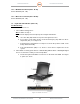
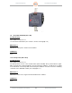
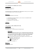
Figure 8. 24VDC Power Supply
1.9. UPS, 2000/1800 KVA (Unit 1 A9)
Troubleshooting:
SD-135956-100 Sheet 2 of 3
Use Vendor Documentation (See Volume 2, Section 4, Paragraph 1.9)
Maintenance:
Maintain the UPS per the Vendor Documentation.
Calibration:
None
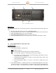
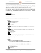
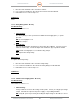
1.10. E-Stop Panel (Unit 1 A12)
Troubleshooting:
SD-135956-100 Sheet 2 of 3
The E-Stop Panel consists of two circuit breakers (CB1 and CB2), three power indicators (Input,
Main, and Pedestal), and E-Stop Button, and an E-Stop Reset Button. Troubleshoot according
to the Schematic. The E-Stop Button and E-Stop Reset Button control the Contactor and Relay
on the DC Power Distribution Plate (See Paragraph 1.11).
Maintenance:
Maintenance will consist of typical electrical maintenance activities.
Calibration:
None