
User's Manual Part 1

T
ECHNICAL
D
OCUMENTATION
P
ROTECTING
P
EOPLE AND
A
SSETS
®
D
ATE
:
22
M
ARCH
2017
|
V
ERSION
:
1.4
17
R
ANGER
-X5
R
ADAR
S
YSTEM
T
ROUBLESHOOTING
,
M
AINTENANCE
,
AND
C
ALIBRATION
EEC
®
|
C
OMPANY
P
ROPRIETARY
SD-135956-100 Sheet 2 of 3
SD-133116-100 Sheet 1 of 1
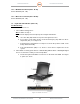
Troubleshooting:
1. Initial Testing:
Using a voltmeter, measure the voltage of PS1 (Unit 1 A8 PS1) to verify proper voltage
output. Check at the output of the power supply. Is it providing 24 VDC?
NO: Verify AC power is present by measuring the input voltage on the input side of the
Power Supply. If AC voltage is present, replace the failed Power Supply.
YES: Go to Step 2.
2. Check the Ethernet Switch:
Is the Ethernet Switch powered on?
NO: Check the fuse (F3) between the power supply and Ethernet switch.
YES: End Step.
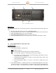
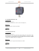
Maintenance:
If the Power Supply does not perform properly, replace the unit.
1. Disconnect all cables from the Power Supply.
2. Use a screwdriver to disconnect from the DIN rail.
3. Pull the Power Supply from the DIN rail.
4. Reinstall the Power Supply in reverse order of steps 1-3.
Calibration:
In the event of a total failure of the 24 VDC Power Supply, the Fiber Optic Media Converter will not function
Procedure:
Adjust the 24VDC Power Supplies to 24VDC after replacement. To make the adjustment:
1) Ensure AC Power is available. The “DC ON” LED will illuminate.
2) Connect a Volt Meter to the output of the Power Supply.
3) Measure the voltage.
4) Using the Vout ADJ., adjust the voltage upward (clockwise turns) or downward (counter
clockwise turns) until the voltage readout is 24.0 VDC on the Volt Meter. Note: The
operational range of the voltage is 23.0 VDC to 24.6 VDC.
5) Cleanup the work area and return the Radar System to normal operations.