
User's Manual Part 1

T
ECHNICAL
D
OCUMENTATION
P
ROTECTING
P
EOPLE AND
A
SSETS
®
D
ATE
:
22
M
ARCH
2017
|
V
ERSION
:
1.4
16
R
ANGER
-X5
R
ADAR
S
YSTEM
T
ROUBLESHOOTING
,
M
AINTENANCE
,
AND
C
ALIBRATION
EEC
®
|
C
OMPANY
P
ROPRIETARY
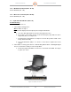
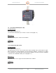
1.7. Fiber-Optic Coupler (Unit 1 A7)
Troubleshooting:
SD-133116-100 Sheet 1 of 1
If the Fiber-Optic network isn’t connected, check this unit as a last resort. There are several
spare ports. This is a passive device and it should not fail during the operational life of the radar
system.
Maintenance:
None
Calibration:
None
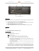
1.8. Fiber Optic Media Converter Assembly (Unit 1 A8)
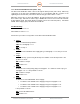
1.8.1. 7-Port Ethernet Switch with 1-Fiber Optic Port (Unit 1 A8 A1)
Troubleshooting:
SD-133116-100 Sheet 1 of 1
1. Is the Ethernet Switch receiving power?
YES: Continue to Step 2.
NO: Check the input power using the Schematics.
a. Check the 24VDC Power at the input of the Ethernet.
b. If power is present, proceed to Step 2.
2. If the Ethernet Switch is receiving power but not communicating with any of the units,
then there is likely a connection problem. Replace the Ethernet Switch.
Maintenance:
If the Ethernet Switch does not perform properly, replace the unit.
1. Disconnect all cables from the Ethernet Switch.
2. Use a screwdriver to disconnect from the DIN rail.
3. Pull the Ethernet Switch from the DIN rail.
4. Reinstall the Ethernet Switch in reverse order of steps 1-3.
Calibration:
None
1.8.2. 24VDC Power Supply (Unit 1 A8 PS1)
Troubleshooting: