
User's Manual Part 1

T
ECHNICAL
D
OCUMENTATION
P
ROTECTING
P
EOPLE AND
A
SSETS
®
D
ATE
:
22
M
ARCH
2017
|
V
ERSION
:
1.4
12
R
ANGER
-X5
R
ADAR
S
YSTEM
T
ROUBLESHOOTING
,
M
AINTENANCE
,
AND
C
ALIBRATION
EEC
®
|
C
OMPANY
P
ROPRIETARY
1.2.2. IQ2 DSP PCIe Board (Unit 1 A2 A2)
Part of IQ2-DSP (Unit 1 A2)
1.2.3. IQ2 Connector Panel (Unit 1 A2 A3)
Part of IQ2-DSP (Unit 1 A2)
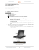
1.3. Keyboard Video Monitor (Unit 1 A3)
Troubleshooting:
SD-135956-100 Sheet 2 of 3
1. Is the KVM receiving power?
YES: Continue to Step 2.
NO: Check the input power and output power using the Schematics.
a. Go to the UPS (A9) and measure power at Segment 2, Port 2.
b. If no power is on the UPS, check to ensure the Emergency Stop button on the S-
Stop Panel (A11) is not depressed.
c. If the Emergency Stop button is not depressed, check the position of CB1 on the
E-Stop Panel Assembly.
d. If the Circuit Breaker (CB1) is on, check to ensure there is input Power to the
system.
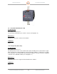
2. If the KVM is receiving power but not communicating with the RCU or IQ2-Digital Signal
Processor, then there is likely a connection problem.
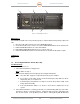
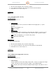
a. Check the Keyboard and Mouse Connectors on the back of the KVM. See Figure
6, points 5, 6, and 7.
Figure 6. KVM Connections