
User's Manual


ISSUE/REVISION DATE: 12 March 2007 TECHNICAL MANUAL
CHAPTER 2 BASE TRANSMITTER (MAGNETRON)
ISO 9001:2000 PROPRIETARY
Base Transmitter (Magnetron) 2-16 ENTERPRISE ELECTRONICS CORPORATION
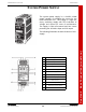
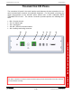
TRANSMITTER I/O PANEL
The transmitter I/O panel is the main interface point between the base transmitter, the ex-
ternal communication network, and pedestal equipment. For full details concerning the
signal characteristics of the interface panel, please refer to EEC Publication BASE
TRANSMITTER I/O ICD. The various connectors provided perform the following func-
tions.
• E1 – Chassis Ground
• J1 – AC Mains Input
• J2 – Unassigned
• J3 – J5 – Ethernet Communications
• J6 – Auxiliary monitoring connector
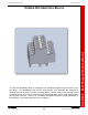
The Base Transmitter I/O Interface Control Document (ICD) provides textual detail of the Base Transmit-
ter I/O Modulator Assembly.
E1 J1 J2 J3 J4 J5 J6