
User's Manual


ISSUE/REVISION DATE: 12 March 2007 TECHNICAL MANUAL
CHAPTER 2 BASE TRANSMITTER (MAGNETRON)
ISO 9001:2000 PROPRIETARY
Base Transmitter (Magnetron) 2-14 ENTERPRISE ELECTRONICS CORPORATION
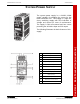
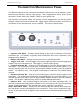
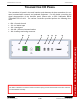
TRANSMITTER MAINTENANCE PANEL
Two different options for the transmitter maintenance panel exist; one incorporates a ped-
estal intercom function, and the other doesn't. Both configurations will be shown in this
document. Please refer to the FAMILY TREE for your specific unit.
The functions of this panel, which are common to both configurations, are run-time meter
displays, forward and reverse detected RF, trigger output, Ethernet interface, and USB 2.0
connectors for the optional touch screen computer. The panel is shown below.
• Operate Time Meter – Provides visual display of the hours of operation of the base
transmitter unit. This display is typically used to determine the hours of operation of the
Magnetron tube filaments.
• Radiate Time Meter – Display of hours the unit is in transmit operation.
• Trigger Test Jack – Used to trigger external test equipment by the system trigger gen-
erated in the base transmitter unit. This trigger is +5VDC positive going.
• Forward Detected RF – Connect to an oscilloscope to view the detected pulse of the
transmitter. The oscilloscope should have a bandwidth limit set at around 20MHz, or an
external low-pass filter with a cutoff of approximately 20MHz should be used for optimum
results. For Indication only. See Chapter 6 Maintenance section for Pulse Width Meas-
urement.
• Reverse Detected RF – Connect to an oscilloscope to view the detected pulse of the
transmitter. The oscilloscope should have a bandwidth limit set at around 20MHz, or an
external low-pass filter with a cutoff of approximately 20MHz should be used for optimum
results. See Chapter 6 Maintenance section for Pulse Width Measurement.
• Ethernet Port – Use for direct Ethernet connection to the base transmitter hub. An
external computer with optional EEC software can be connected to this port for transmitter
control during maintenance if the optional touch screen interface is not utilized.
USB 1 and USB 2 Ports – These ports are used only with the optional touch screen op-
tion and allows a mouse and keyboard to be connected. These are not required for regu-
lar use of the touch screen, though the user may be more comfortable with this method of
control.