
User`s guide


Viewing Chassis Information 2-9
The FN100 Chassis View
I/F Type
If you choose the I/F T
ype mode, the port text boxes will display the port type
(e.g., Eth, PPP) of each port, as determined by the port’s MIB II ifType value.
Port Status Color Codes
The B
ridge port display mode incorporates the following color-coding scheme:
green = FWD, blue = DIS, magenta = LIS/LRN, orange = BLK, red = BRK, and
gray = UNK.
The Ad
min and Operator port display modes use the following color-coding
scheme: green = ON, red = OFF.
For the L
oad, Errors, I/F Mapping, I/F Speed, and I/F Type port display modes,
color codes will continue to reflect the most recently selected mode which
incorporates its own color coding scheme.
The Chassis Manager Window
The FN100 draws its functionality from a collection of proprietary MIBs and IETF
RFCs, and organizes its MIB data into a series of components. A MIB component
is a logical grouping of MIB data; each group controls a defined set of objects. For
example, FN100 bridging information is organized into its own component. Note,
too, that there is no one-to-one correspondence between MIBs and MIB
components; a single MIB component might contain objects from several different
proprietary MIBs and RFCs.
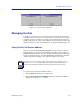
The Chassis Manager window, Figure 2-3, is a read-only window that displays the
MIBs and the MIB components — and, therefore, the functionality — supported
by the currently monitored device.
To view the Chassis Manager window:
1. Click on H
elp on the menu bar at the top of the Chassis View window.
2. Drag down to M
IBs Supported, and release.